Descrizione
What the Crawler Crane Boom Hoist Cylinder Does — and Why It’s the Hardest-Working Cylinder on the Machine
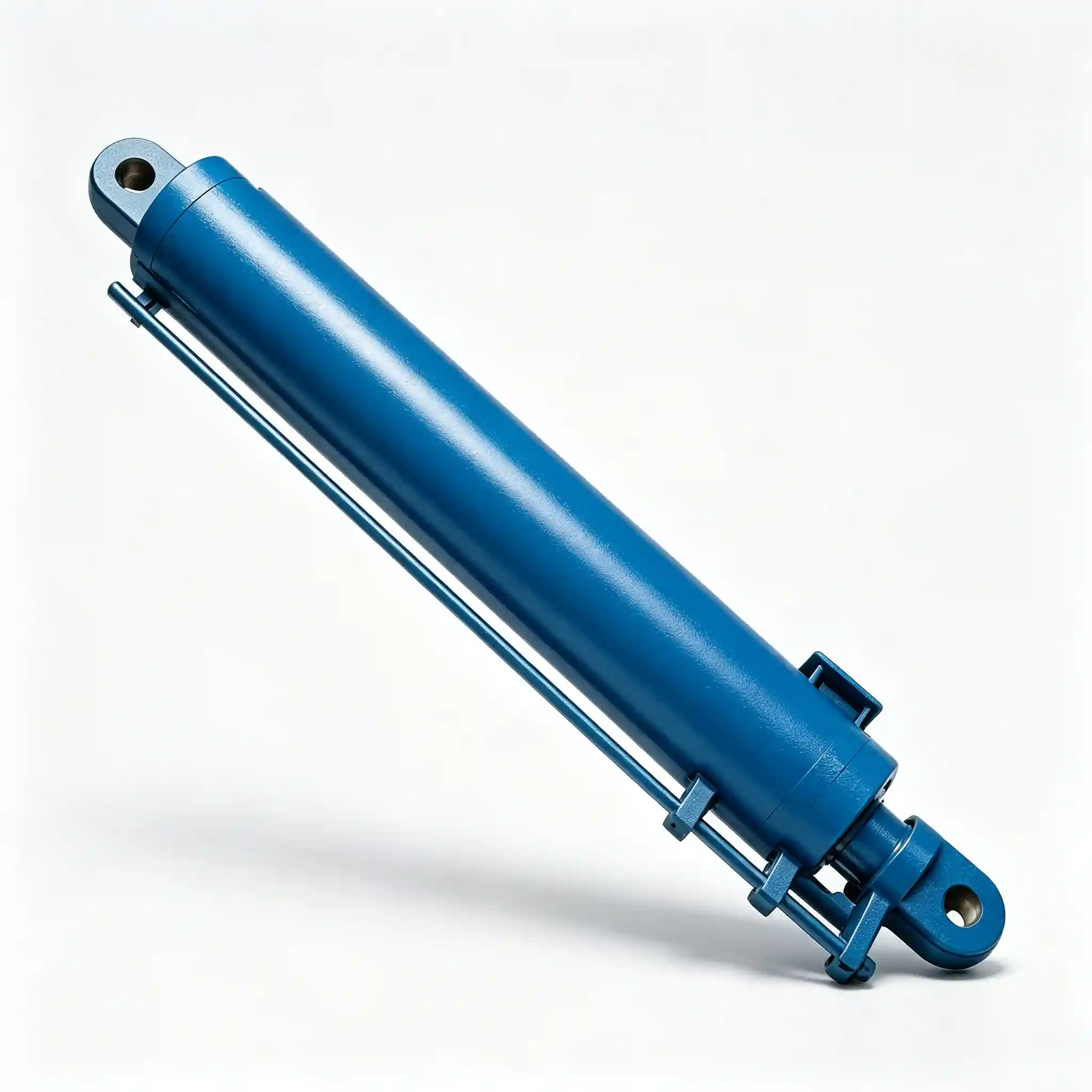
On a crawler crane, the boom hoist hydraulic cylinder has the most unforgiving job description in the entire hydraulic system: raise and lower the boom under full rated load, hold position without drift under sustained load, and do it repeatedly across years of heavy construction, infrastructure, and lifting operations. The HCYY11112018 is built specifically for this role — a Φ280 mm bore, 2200 mm stroke cylinder rated at 31.5 MPa and weighing just over a metric tonne.
The boom hoist function — sometimes called luffing — controls the angle of the boom relative to the crane’s upper structure. Every degree of change in boom angle shifts the effective load radius and alters the overturning moment on the crane. The crane luffing cylinder is therefore not just a lifting actuator; it’s a precision positioning device that determines safe working radius on every lift. Small errors in boom angle translate directly into load chart violations and structural overload risk.
At 40 MPa maximum withstand pressure — 27% above rated working pressure — and a 3000 mm installation distance, the HCYY11112018 is specified for crawler cranes in the 100–500 tonne capacity class where the loads being managed, and the consequences of cylinder failure, are both in a category of their own.
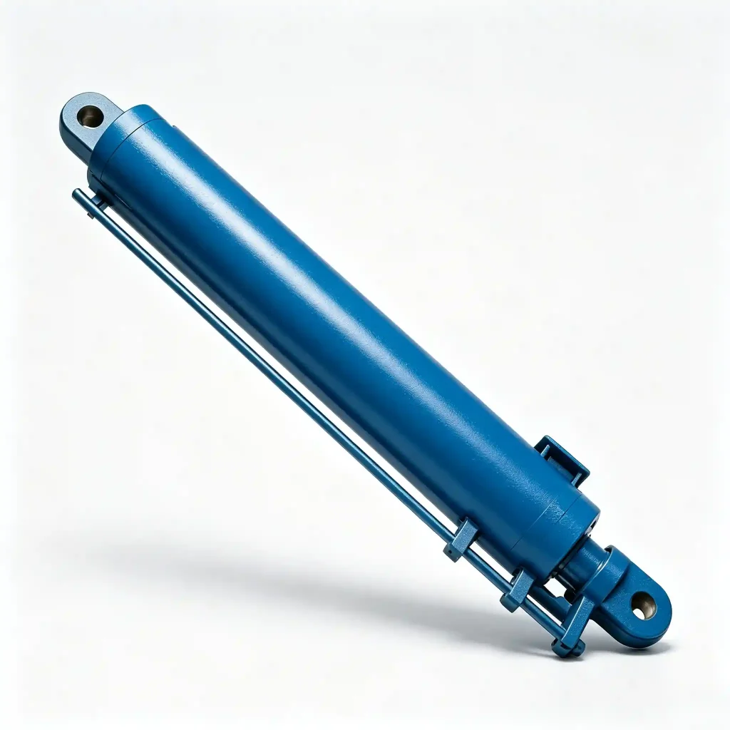
Crawler Crane Hydraulic Cylinder Installation Positions
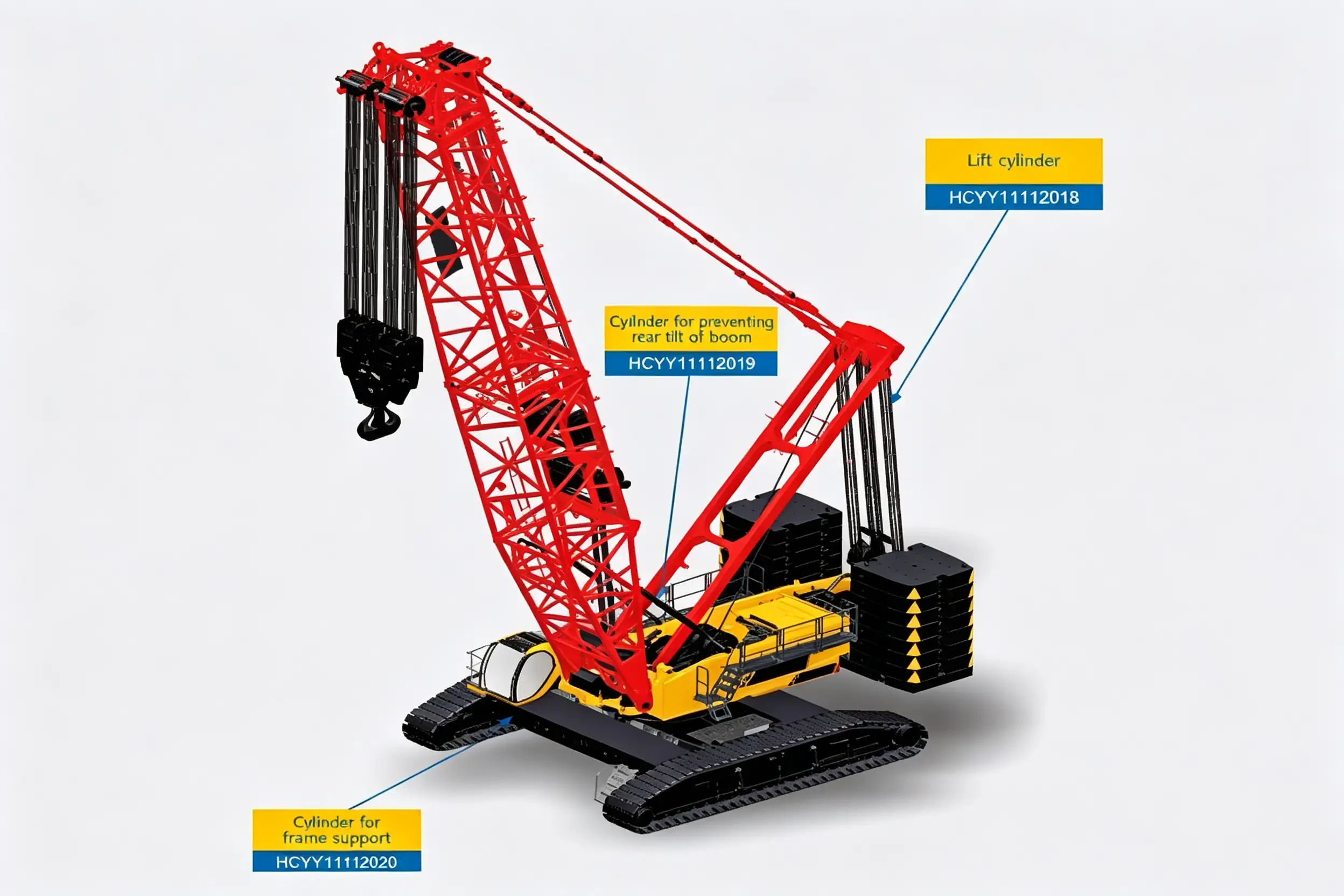
The boom hoist cylinder connects the upper structure to the boom foot — extending to raise the boom angle, retracting to lower it under controlled load.
Technical Specifications — HCYY11112018 Boom Hoist Hydraulic Cylinder
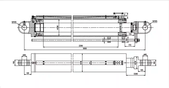
| Parameter | Value | Engineering Context |
|---|---|---|
| Model | HCYY11112018 | Crawler crane boom hoist series |
| Bore × Rod × Stroke | Φ280 × Φ160 × 2200 mm | Large-bore long-stroke for maximum luffing torque |
| Working Pressure | 31.5 MPa | Push force ≈ 1,939 kN at rated pressure |
| Max Withstand Pressure | 40 MPa | 27% overpressure margin; each unit hydrostatically tested |
| Stroke (Trip) | 2200 mm | Controls full angular range of boom luffing travel |
| Installation Distance | 3000 mm | Pin-to-pin (retracted); critical for boom geometry |
| Weight | 1,003 kg | Heaviest cylinder in the crawler crane hydraulic system |
Why a Φ280 Bore and 40 MPa Burst Rating Matter on a Heavy Crawler Crane
A Φ280 mm bore at 31.5 MPa produces a calculated push force of approximately 1,939 kN — close to 200 tonnes of linear force. That force, acting through the boom pivot arm, creates the torque needed to raise and hold the boom against the combined weight of the boom structure, rigging, and suspended load. On large crawler cranes, the boom assembly alone can weigh 30–80 tonnes before any load is attached; the hoist cylinder must overcome that dead weight on every single raise cycle.
The Φ160 mm rod — a 4:2.3 bore-to-rod ratio — is sized to handle the compressive buckling load across a 2200 mm stroke under eccentric loading conditions. During boom lowering, the cylinder transitions from a tension-loaded (extending against boom weight) to a compression-loaded state as the boom weight reverses through the pivot geometry. This reversal creates a column buckling risk on the rod that undersized designs fail to account for. The Φ160 rod on the HCYY11112018 is calculated to maintain a minimum Euler buckling safety factor of 3.5 across the full stroke range.
The 40 MPa maximum withstand pressure — 27% above the 31.5 MPa working rating — is not arbitrary. Crawler crane hydraulic systems regularly experience pressure spikes during boom raise initiation (load break-out force), sudden load swings that shift center of gravity, and emergency stop events. The 8.5 MPa margin between working and withstand pressure absorbs these transients without seal extrusion or bore distortion.
The 3000 mm installation distance is the geometric foundation of the boom luffing system. It determines the mechanical advantage at every boom angle — change it, and you change the load chart. This is why replacement cylinders must match the OEM installation distance exactly; a few millimetres of variation ripples into measurable changes in rated lift capacity at working radius.
Where the Crawler Crane Boom Hoist Cylinder Is Deployed
The HCYY11112018 is specified for the boom hoist position on lattice-boom crawler cranes operating across the following sectors:
- Heavy civil and infrastructure construction — bridge beam installation, dam construction, and large-span structure lifts where boom angle control determines safe working radius on every pick
- Oil, gas, and petrochemical plant construction — module lifts and vessel installations where sustained load holding at precise boom angles is required for extended periods
- Offshore and marine heavy lift — port equipment installation, jacket setting, and subsea module handling where sea-state induced dynamic loading adds to the static load
- Wind energy installation — nacelle and blade lifts where the boom must hold a fixed angle for extended periods while rigging crews position the load
- Nuclear and power plant maintenance — controlled heavy lifts in confined or sensitive environments where reliable load-holding without drift is a safety requirement, not a preference
Construction and Material Specification — Built for the Loads That Don’t Forgive Shortcuts
Cylinder Barrel
Seamless forged steel tube (ST52 / 27SiMn), precision-honed bore Ra ≤ 0.4 μm. Wall thickness verified by finite element analysis for 40 MPa burst with minimum safety factor of 2.5 on yield.
Piston Rod
Φ160 mm, 42CrMo4 alloy steel, induction-hardened and hard-chrome plated ≥ 30 μm. Slenderness ratio engineered against Euler column buckling at full 2200 mm extension under eccentric loading.
Seal Package
Hallite or equivalent PU/PTFE composite piston seal with bronze-filled backup rings. Rod seal with double-lip wiper and anti-extrusion ring. Rated −30 °C to +90 °C, compatible with HM/HV mineral hydraulic oil.
End Mounts
Heavy-duty forged-steel clevis and pin-eye ends, machined from 42CrMo4. Pin bore tolerance H7, spherical bearing option available for misalignment up to ±3° in service.
Load-Holding Valve
Integral counterbalance valve (pilot-operated check) mounted directly on the cylinder port block. Prevents boom drop on hydraulic line failure — a mandatory safety feature on all crane luffing circuits.
Factory Testing
Full stroke cycle test (5 cycles, no-load and loaded), hydrostatic hold at 40 MPa for 10 minutes, zero-leakage verification at 31.5 MPa. Individual test certificate issued per cylinder.
Installation and Replacement — What You Need to Know Before the Crane Goes Down
A 1,003 kg cylinder replacement on a crawler crane is a planned maintenance event, not a field improvisation. Key considerations:
- Verify the 3000 mm installation distance pin-to-pin before ordering — boom structure wear at the pivot bushing can introduce 5–20 mm of false clearance that shifts the effective installation dimension.
- Inspect pivot pin and spherical bearing condition at replacement time. Worn bearings transmit side-loading directly into the cylinder rod gland, the leading cause of accelerated rod seal wear on large crane cylinders.
- Commission the counterbalance valve setting after installation. The CBV crack pressure must be set to 1.3× maximum load-induced pressure — too low causes boom creep, too high causes pressure spike on lowering initiation.
- Bleed systematically — at 2200 mm stroke, entrapped air volumes are significant. Cycle the cylinder 5–10 times at low pressure before applying full load; any remaining air will cause hammer at the end of the raise stroke under full boom weight.
- Use a certified lifting fixture rated for ≥ 2 tonnes to handle the cylinder during installation — the 1,003 kg weight plus rigging hardware exceeds standard maintenance crane ratings on many job sites.
Common Questions — Crawler Crane Boom Hoist Hydraulic Cylinder
Does the boom hoist cylinder need a counterbalance valve, and is one included?
Yes to both. A counterbalance valve (CBV) is mandatory on any crane luffing cylinder that supports a suspended load — without it, a hydraulic line failure results in uncontrolled boom drop, which is a fatal risk event in crane operation. The HCYY11112018 is supplied with an integral pilot-operated counterbalance valve pre-mounted on the cap-end port block. The CBV is factory-set to 1.3× the maximum static load pressure and is individually tested before shipment. If your system design requires a specific CBV setting or brand, specify at order — we can accommodate most crane OEM requirements.
The boom is drifting down slowly under load — is this the cylinder?
Possibly, but the counterbalance valve is a more likely culprit and should be checked first. Boom drift on a properly functioning CBV-equipped cylinder is almost always a CBV seat leak (contamination or seat wear) rather than a piston seal bypass. Isolate the cylinder by capping both ports and observing drift — if drift stops, the CBV or the control valve is leaking to tank. If drift continues with ports capped, the piston seal has bypassed and the cylinder needs reseal. Never operate a crane with unexplained boom drift — this is a safety-critical fault requiring immediate investigation.
What causes rod seal failure on a boom hoist cylinder specifically?
Four field-confirmed causes in order of frequency: (1) Worn or seized spherical bearing at the rod-end pin, causing the rod to enter the gland at an angle — the most common cause on cranes with high operating hours. (2) Rod surface pitting from condensation trapped inside the cylinder during extended idle periods in humid environments — moisture attacks the chrome through microscopic defects. (3) Side-loading from boom misalignment during re-pinning, which scores the chrome on one side. (4) Contaminated hydraulic oil above ISO cleanliness code 18/16/13 — abrasive particles accelerate seal lip wear to a fraction of normal service life. On a cylinder this size, a seal replacement is a significant maintenance event — the contamination root cause is worth investigating before re-sealing.
Can the HCYY11112018 be re-chromed rather than replaced if the rod is pitted?
Yes, rod re-chroming is viable when: the base steel shows no pitting below the chrome layer, the rod is not bent (runout < 0.3 mm/m), and the chrome loss is surface-level rather than through substrate corrosion. The process involves stripping the old chrome, grinding to remove any corrosion, re-plating to ≥ 30 μm, and final-grinding to dimensional tolerance. A re-chromed rod on a safety-critical crane application should be MPI (magnetic particle inspection) tested post-grinding to confirm no sub-surface cracks before return to service. We can supply a replacement rod assembly as an alternative if re-chroming lead time is a constraint.
What’s the typical lead time for the HCYY11112018, and can you expedite?
Standard lead time for a new HCYY11112018 is 6–10 weeks from order confirmation, covering material procurement, machining, assembly, and testing. For fleet operators with multiple crawler cranes, we recommend maintaining at least one cylinder in buffer stock given the downtime cost of a crane out of service. Expedited production (4–5 weeks) is available at a surcharge for confirmed urgent orders — contact us with your required delivery date and we will confirm feasibility. Seal kits and rod assemblies ship from stock with 2–3 day lead time.
Ready to Source the HCYY11112018 — or Need a Technical Quotation?
We supply crawler crane boom hoist cylinders to crane OEMs, fleet operators, and heavy-lift contractors across North America, Europe, the Middle East, and Australia. Full dimensional drawings, hydrostatic test certificates, and individual serial-number traceability are standard. Seal kits, rod assemblies, and counterbalance valve packages available separately.
Model: HCYY11112018 · Φ280×Φ160×2200 · 31.5 MPa / 40 MPa · 2200 mm stroke · 3000 mm installation distance · 1,003 kg