Description
Model: HCYY11112024
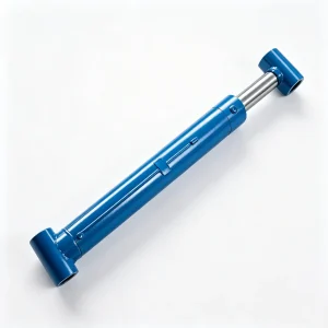
Crane Front Outrigger Extension Hydraulic Cylinder
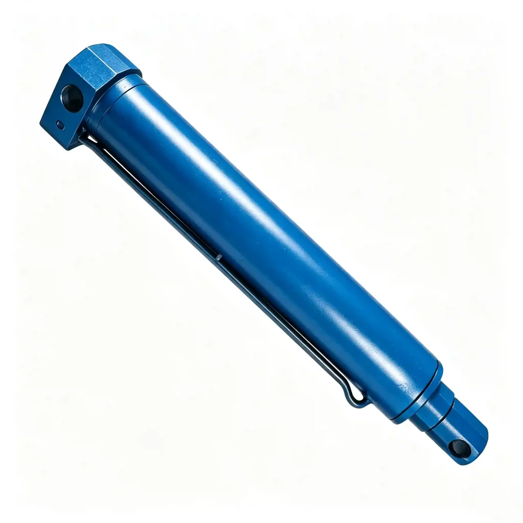
The crane front outrigger extension hydraulic cylinder HCYY11112024 is purpose-designed for the front outrigger beam position on mobile cranes, where the beam geometry, available installation space, and required extension travel differ from the rear outrigger circuit. With a Φ40mm bore, a 1,855mm stroke, and a working pressure of 12MPa, this cylinder delivers a stroke-to-bore ratio of over 46:1 — making rod buckling resistance and guide bearing design the dominant engineering considerations in its specification.
Key Specifications at a Glance
- Bore × Rod × Stroke: Φ40 × Φ30 × 1855 mm
- Working Pressure: 12 MPa
- Max Withstand Pressure: 18 MPa
- Installation Distance: 2,057 mm
- Weight: 24 kg
Why the Front Outrigger Extension Cylinder Has a Different Specification to the Rear — and Why It Matters
On many mobile crane designs, the front and rear outrigger systems are not symmetrical. The crane’s centre of gravity, counterweight position, and boom pivot location mean that the front outrigger beams may need to extend further, retract into a different profile, or operate at a lower pressure circuit than the rear. The HCYY11112024 reflects this front-specific geometry: its 1,855mm stroke is notably longer than the 635mm stroke of the rear outrigger extension cylinder (HCYY11112026), and its 12MPa working pressure operates on a lower-pressure hydraulic circuit than the main boom or jack circuits.
The Φ40mm bore at 12MPa generates approximately 15 kN of push force — sufficient for extending a front outrigger beam whose beam weight and sliding friction are lower than a larger rear beam, due to the lighter structural requirements of the front outrigger position on this crane class. The engineering challenge is not generating adequate force; at these parameters, the force calculation is straightforward. The challenge is maintaining a Φ30mm rod straight and buckling-free over a 1,855mm stroke — a slenderness ratio that requires careful attention to guide bearing design and mounting constraint conditions.
At just 24kg, the HCYY11112024 is the lightest cylinder in the front/rear outrigger group by a significant margin. This weight is consistent with its smaller bore and thinner walls, but it also means the cylinder must be handled carefully during installation and removal — lateral force applied to the rod during handling can cause permanent rod deflection that compromises seal life.
Installation Position Diagram — HCYY11112024 / 25 / 26 / 27 on Crane
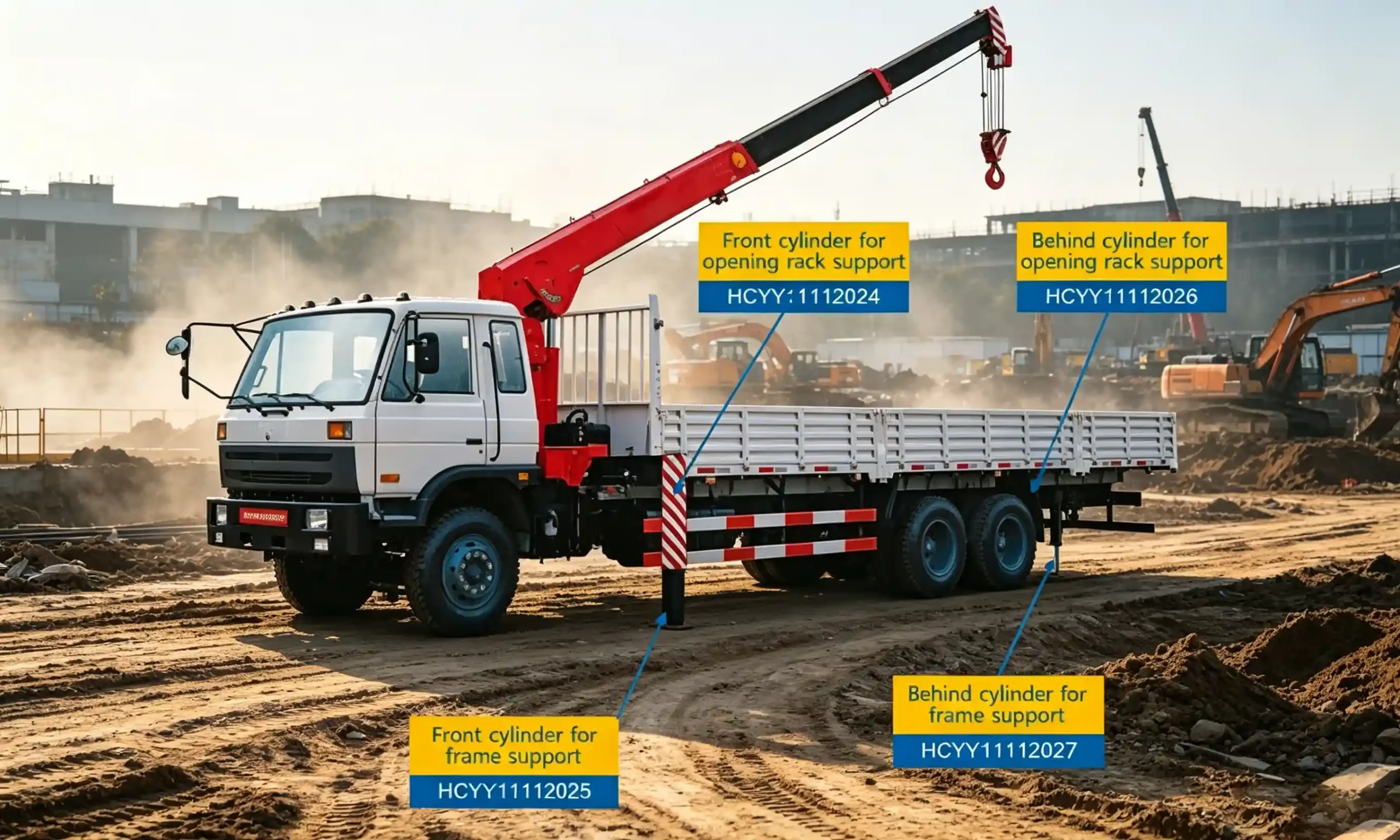
Diagram showing the positions of the front outrigger extension cylinder (HCYY11112024), front outrigger jack cylinder (HCYY11112025), rear outrigger extension cylinder (HCYY11112026), and rear outrigger jack cylinder (HCYY11112027) within the crane chassis structure.
Full Technical Specifications for the Long Stroke Front Stabilizer Beam Hydraulic Cylinder
The HCYY11112024 is unusual in this product family for its combination of small bore, low working pressure, and very long stroke. Each parameter has a specific reason — understanding them prevents specification errors when sourcing a replacement unit.
| Parameter | Value | Engineering Significance |
|---|---|---|
| Model | HCYY11112024 | Unique model identifier. Note the prefix differs slightly from the HCYY111-series — confirm model number on procurement documents to avoid ordering errors. |
| Specifications | Φ40 × Φ30 × 1855 mm | Bore × Rod × Stroke. The Φ30mm rod with a 1,855mm stroke gives a slenderness ratio demanding careful buckling analysis. Both ends are constrained (pin-pinned mounting), which halves the effective buckling length compared to a cantilevered rod. |
| Working Pressure | 12 MPa | The lowest working pressure in this cylinder series. At Φ40mm bore (effective area ≈ 1,257 mm²), this yields approximately 15 kN of push force — calibrated to the lighter front outrigger beam structure on this crane design. |
| Max Withstand Pressure | 18 MPa | 1.5× working pressure safety factor — consistent with the outrigger extension cylinder series. Protects against end-of-travel pressure spikes when the beam reaches its travel stop at full extension. |
| Stroke | 1,855 mm | The longest stroke in the front/rear outrigger cylinder group. Sets the maximum front outrigger beam spread at the front axle position — a key variable in the crane’s front-sector rated lift capacity. |
| Installation Distance | 2,057 mm | Pin-to-pin retracted length of 2,057mm — the longest installation distance in this cylinder group. Confirms this cylinder spans a significant portion of the front outrigger beam even when fully retracted. |
| Weight | 24 kg | Lightest cylinder in the front/rear outrigger group. Single-person installation is possible but two-person handling is recommended to avoid lateral rod loading during assembly — critical for a long thin rod that is sensitive to permanent set. |
HCYY11112024 CAD Drawing Reference

Full-dimension CAD drawing available in DXF and PDF format. Provide your crane model and outrigger position details to receive the dimensional verification package.
Rod Buckling Analysis for Long Stroke Outrigger Extension Cylinders: Why Φ30mm Over 1,855mm Is Engineered, Not Oversized
A Φ30mm rod spanning 1,855mm under compressive load is the parameter that draws the most engineering scrutiny on this cylinder. At first glance it appears slender — and it is, by the standards of a pressurised cylinder rod. Understanding why this configuration is both deliberate and structurally sound requires examining how buckling analysis is applied to guided cylinder rods.
The Euler critical buckling load for a slender column is governed by the effective length, which depends on the end constraint conditions. For a hydraulic cylinder rod mounted pin-pin at both ends (clevis or spherical eye at the rod end, trunnion or clevis at the head end), the effective buckling length is the full rod extension length. For the HCYY11112024, this is the stroke length plus the rod length inside the cylinder at full extension — approximately equal to the installation distance of 2,057mm.
At 12MPa working pressure on a Φ40mm bore, the maximum compressive load on the rod is approximately 15 kN. Applying Euler’s formula to a Φ30mm solid steel rod (second moment of area ≈ 39,761 mm⁴, E = 210 GPa) with an effective length of 2,057mm and pin-pin end conditions gives a critical buckling load of approximately 19.5 kN — providing a buckling safety factor of approximately 1.3× above the maximum hydraulic thrust. For an outrigger extension cylinder where the beam guides the rod laterally inside the box section, this safety factor is considered appropriate — the beam itself provides additional lateral support to the cylinder and rod system that Euler’s free-column calculation does not account for.
The key practical implication: this cylinder must always be installed with both ends correctly pinned and with the rod guided by the outrigger beam structure. Operating it in a configuration where the rod extends freely without lateral beam guidance — for example, during bench testing outside the beam — creates a buckling risk at working pressure that does not exist during normal crane operation.
Front vs Rear Outrigger Extension Cylinders: Key Differences That Prevent Cross-Fitting Errors
The front outrigger extension cylinder (HCYY11112024) and the rear outrigger extension cylinder (HCYY11112026) share the same bore and pressure ratings, but differ substantially in stroke and installation distance. This table clarifies the differences that matter most for procurement:
| Parameter | Front (HCYY11112024) | Rear (HCYY11112026) |
|---|---|---|
| Bore × Rod | Φ40 × Φ30 | Φ40 × Φ25 |
| Stroke | 1,855 mm | 635 mm |
| Installation Distance | 2,057 mm | 840 mm |
| Working Pressure | 12 MPa | 12 MPa |
| Weight | 24 kg | 9 kg |
The front cylinder’s stroke is nearly 3× the rear’s. Fitting a rear cylinder in a front position results in insufficient outrigger spread — a load chart violation that may not be immediately obvious to the crane operator.
Typical Applications for Front Leg Extension Actuators on Mobile and Truck-Mounted Cranes
- Truck-mounted cranes with asymmetric outrigger geometry: Where the front outrigger beams extend further than the rear to compensate for boom overhang and front-heavy load moment. The 1,855mm stroke is sized for this wider front spread requirement.
- Telescopic boom cranes, 25t–80t class: Front outrigger spread is a primary variable in the front-sector load chart. A cylinder that cannot achieve full stroke reduces the rated front-sector capacity, creating an invisible de-rating that operators may not identify without measurement.
- Cranes with H-frame front outrigger layout: Where two front extension cylinders work in parallel and must extend symmetrically to avoid chassis twist during deployment.
- OEM crane manufacturing: First-fit supply for new crane builds requiring confirmed dimensional accuracy and material certification for production line assembly.
- Fleet maintenance and MRO: Replacement of cylinders with bent rods, scored bores, or failed seals. Given the slender rod dimensions, bent rod replacement is more common in this cylinder size than in larger-bore models — lateral handling damage during field maintenance is a frequent cause.
Construction Standards for Long-Stroke Small-Bore Front Outrigger Extension Cylinders
Small bore, long stroke cylinders present manufacturing challenges that larger-bore units do not: honing a Φ40mm bore to consistent roundness over the full barrel length requires precision tooling, and chrome plating a Φ30mm rod uniformly along its full length demands controlled bath chemistry and rack geometry. These are not trivial manufacturing tasks — the quality of execution here directly determines cylinder service life.
Barrel Honing Precision
The Φ40mm bore is honed to Ra 0.2–0.4μm over the full barrel length. At this small diameter, maintaining cylindricity within tolerance over the long barrel length is more demanding than for large-bore cylinders. Dimensional verification at multiple points along the bore length is performed before acceptance.
Φ30mm Chrome Rod
Hard chrome plated to 20–25μm on a ground substrate. At Φ30mm diameter, rod straightness must be verified before and after plating — the residual stress introduced by chrome plating can induce slight bow in thin rods if the plating parameters are not controlled. Maximum allowable bow: 0.1mm per 1,000mm rod length.
Guide Bearing Length
The cylinder gland carries a bronze or composite guide bearing whose length is proportioned to the bore diameter and maximum side load. For long-stroke cylinders in guided beam applications, bearing length is increased beyond the minimum to reduce specific bearing pressure and extend the interval between guide wear and seal damage.
Rod Seal Stack
Polyurethane primary rod seal with PTFE backup ring and dual wiper seals. The dual wiper configuration is specified for outrigger cylinders where road debris and mud are regular contaminants. At Φ30mm rod diameter, seal groove dimensions are tighter than larger bores — seal kits are model-specific and not interchangeable with other bore sizes.
End Eye / Pin Interface
Clevis or spherical bearing ends machined from forged steel, heat-treated at the pin contact surface. The spherical bearing option allows ±3–5° misalignment to accommodate the slight angular shift as the outrigger beam extends and the cylinder attachment geometry changes through the stroke range.
Pressure Testing
Tested at 18MPa (full maximum withstand pressure) for a minimum 5-minute hold at both full extension and full retraction. Due to the long stroke, the test rig must accommodate the 2,057mm installation distance at retraction — a logistical requirement that confirms test procedures match real installation geometry.
Ordering Checklist for Crane Front Outrigger Extension Cylinder Procurement
Given the unique combination of long stroke and small bore in this cylinder, dimensional verification before ordering is especially important. Confirm the following before placing an order:
- Confirm this is the front (not rear) outrigger position: The front cylinder (HCYY11112024) has a 1,855mm stroke and 2,057mm installation distance. The rear (HCYY11112026) has a 635mm stroke and 840mm installation distance. These are not interchangeable.
- Installation distance at full retraction (2,057mm): Measure the existing cylinder pin-centre to pin-centre with the beam fully retracted and the cylinder at full retraction. This is the parameter that determines whether the replacement unit will fit within the beam’s stowed envelope.
- Pin bore diameters and eye style: Clevis or spherical bearing ends, pin diameter at head end and rod end. On a Φ30mm rod, pin eye geometry is small — confirm dimensions carefully to ensure pin clearance is adequate without excessive play.
- Port specification: Thread type (SAE/BSP/metric) and port location. On a long-stroke cylinder, hose length and routing inside the beam section are affected by port position — confirm with reference to your original cylinder’s port layout.
- Crane make, model, and year: Helps cross-reference known fitment data and catches cases where the same crane model has different cylinder specifications across production years.
Frequently Asked Questions — HCYY11112024 Crane Front Outrigger Extension Hydraulic Cylinder
B2B Procurement & OEM Supply
Source the HCYY11112024 for Your Crane’s Front Outrigger System
Provide your crane make and model, the existing cylinder’s retracted installation distance, and your required quantity. We will confirm dimensional fit, supply a CAD drawing for engineering review, and issue a formal quotation within 24–48 business hours. Seal kits and matched cylinder pairs are also available.