
QD (Quick Detachable) Sprockets
Heavy-duty ANSI-standard sprockets with taper bushing mounting — swap in under 10 minutes, no special tooling. Built for conveyors, agriculture, and industrial drives.
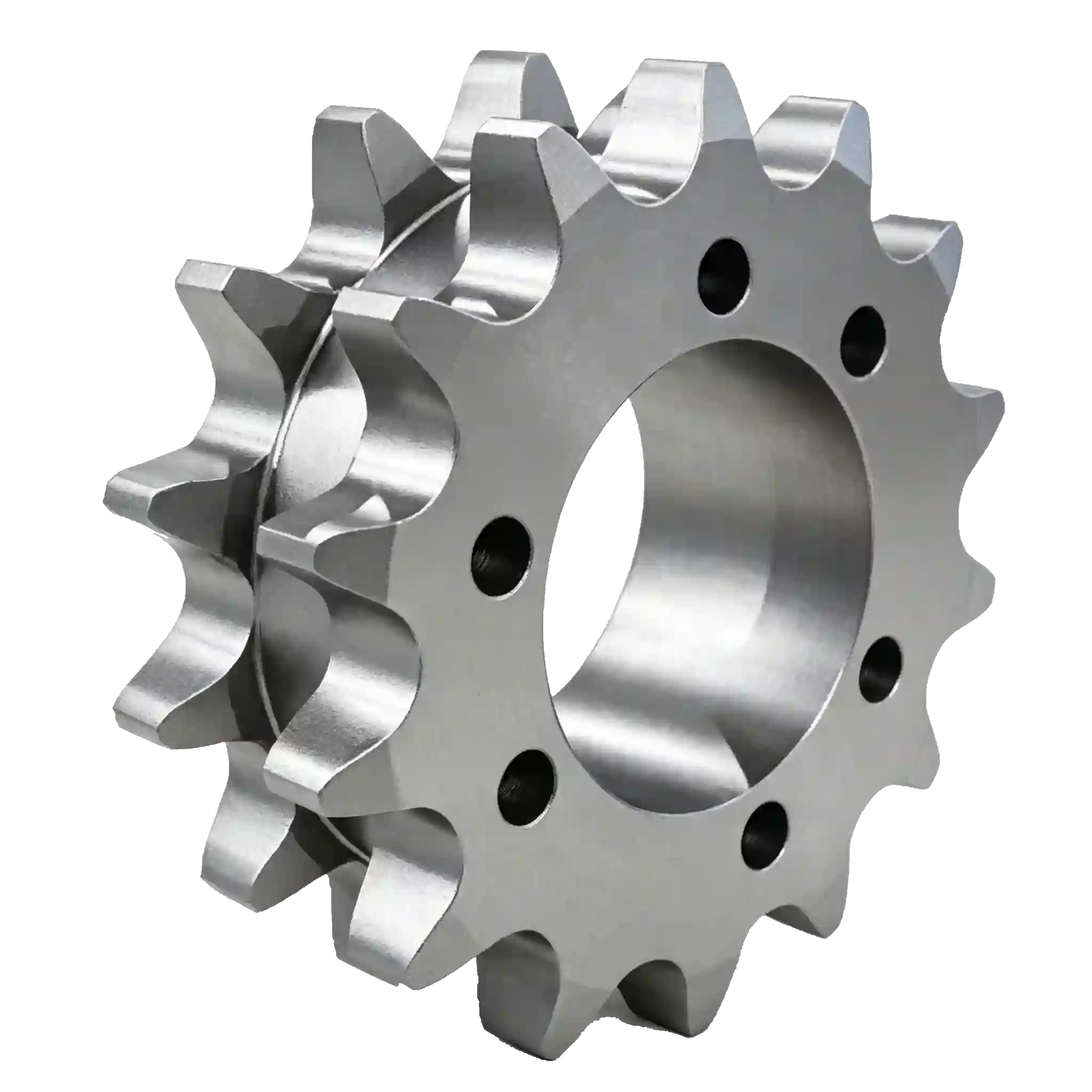
What Is a QD (Quick Detachable) Sprocket?
A QD sprocket incorporates a split taper bushing that locks concentrically onto a shaft when cap screws are tightened — and releases instantly when those same screws are repositioned. Unlike conventional bore-and-keyway sprockets that require hydraulic presses or heating torches, QD-mount sprockets install or remove in minutes with standard hand tools.
This mounting system originated in the 1940s and has become the industry standard for industrial drives requiring frequent sprocket changes, maintenance access, or high-torque shaft retention without fretting corrosion. The split bushing design creates a uniform, concentric grip with TIR under 0.003″ — eliminating eccentricity-driven bearing wear.
Fast installation: Remove or mount in under 10 minutes — no heating, pressing, or pull tooling required.
Concentric shaft grip: Split taper bushing delivers TIR < 0.003″ for vibration-free rotation.
Versatile bushing range: Compatible with standard QD bushings from F to N series, covering shaft diameters 1″–6″.
ANSI-standard profiles: Interchangeable with major OEM brands — drop-in replacements, no modifications needed.
Corrosion-resistant options: Black oxide, zinc, or electroless nickel finish available for washdown environments.
QD Sprocket — Quick Reference Specs
| PARAMETER | SPECIFICATION |
|---|---|
| Material | Ductile Iron (ASTM A536) or AISI 1045 Carbon Steel |
| Tooth Hardness | HRC 45–50 (Induction Hardened) |
| Tooth Tolerance | ±0.002" (CNC machined) |
| Chain Standard | ANSI B29.1 Roller Chain |
| Temp Range | –20°F to 250°F (–29°C to 121°C) |
| Shaft TIR | < 0.003" |
| Shock Load Rating | Up to 200% of rated torque |
| Service Life | 10,000–12,000 hours (normal conditions) |
| Inspection | 100% dimensional before shipment |
メタライトネット
QD Sprocket Product Range
ANSI-compliant heavy-duty QD sprockets in stock — single strand, double strand, and #200 series. Additional tooth counts and custom specs available on request.
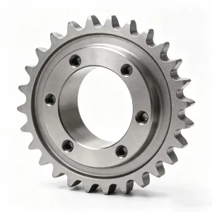
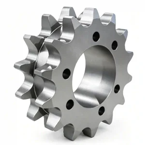
ℹ️ More tooth counts and bushing sizes being added. Contact us for custom specifications or non-standard configurations.
メタライトネット
How QD Taper Bushing Mounting Works
Four steps — no hydraulics, no heating, no specialist trades required.
Position Sprocket on Shaft
Slide the QD bushing into the sprocket hub and align the half-holes in the flange with the threaded holes in the bushing. Position on the shaft at the required axial location.
Insert Cap Screws
Insert cap screws through the unthreaded holes in the bushing flange into the threaded holes in the sprocket hub. Do not tighten yet — leave finger-tight for final alignment.
Align & Tighten
Check sprocket alignment with adjacent sprocket or chain. Tighten cap screws evenly in a star pattern to the specified torque — the taper draws the bushing tight onto the shaft.
Removal in Minutes
To remove: back out cap screws, reinsert them in the threaded jack holes on the bushing flange, and tighten to push the bushing free — no puller, torch, or bearing press needed.
メタライトネット
QD Sprocket Selection Guide
Use this table to match the right QD sprocket to your chain and application requirements.
| MODEL | CHAIN # | PITCH | STRANDS | TOOTH RANGE | MAX BORE | BEST FOR |
|---|---|---|---|---|---|---|
| No.160 Single QD | ANSI #160 | 2" | Single | 35T – 60T | 6" | Standard industrial drives, packaging, agriculture |
| No.160-2 Double QD | ANSI #160-2 | 2" | Duplex | Custom | 6" | High-power drives, mining, heavy conveyors |
| No.200 QD | ANSI #200 | 2.5" | Single | Custom | Custom | Maximum torque applications, heavy industry |
Frequently Asked Questions
Technical answers — direct from our engineering team.
Speak with an Engineer
+1-604 719 2870
RFQ response within 24 hours
What is a QD sprocket and how is it different from a standard sprocket?
A QD (Quick Detachable) sprocket uses a split taper bushing mounted inside the hub. When cap screws are tightened, the bushing compresses concentrically onto the shaft — eliminating shaft press-fit, heating, or specialty pullers. Standard bore sprockets require an interference fit or an external keyway retainer and are significantly slower to install or remove in the field.
Which QD bushing series fits my shaft size?
QD bushings are designated by letter series (F, J, M, N, etc.). The F series accommodates shafts up to roughly 1-7/8″, J up to 2-7/16″, M up to 3-1/2″, and N up to 4-1/2″. Maximum bore capacity increases with each bushing series. Send us your shaft diameter and we’ll confirm the correct bushing specification at no charge.
Can you supply a QD sprocket with a non-standard bore or special keyway?
Yes. We offer custom boring, keyway cutting, and set-screw tapping on any sprocket in our range. Metric keyways, double keyways, and tapered bores are all available. Provide your shaft drawing or dimensions and we’ll confirm lead time — typically 2–3 weeks for custom machining.
What is the torque specification for QD cap screws?
Cap screw torque values vary by bushing series and fastener size. As a general reference: F series 3/8″-16 cap screws torque to approximately 150 in-lbs; M and N series 1/2″-13 cap screws torque to approximately 330 in-lbs. Always refer to the bushing manufacturer’s torque table included with each bushing order. Undertightening causes fretting; overtightening can split the bushing.
Do you offer volume pricing for bulk or OEM orders?
Yes — volume discounts apply at 10, 25, and 50+ unit thresholds depending on model. OEM customers with repeating orders can request blanket pricing agreements. Contact our Richmond team with your estimated annual volume for a tailored pricing proposal.
How do I know when a QD sprocket needs replacing?
Measure tooth thickness using a gear tooth caliper. Replace when thickness drops 8–10% below nominal. Visual signs include a hooked or “shark fin” tooth profile, polished wear steps at the chain roller contact point, and audible chain skipping or slapping under load. Inspect every 500 operating hours in abrasive environments, 1,000 hours in clean industrial settings.