
How to Select a Right Angle Planetary Gearbox: A Step-by-Step Engineering Guide
Gearbox selection looks straightforward until you get into the details. Pick a ratio, check the torque rating, confirm the motor fits—done, right? Not quite. A right angle planetary gearbox has to satisfy five or six independent requirements simultaneously: torque, speed, backlash, radial load, inertia matching, and mounting interface. If any one of those is wrong, the gearbox either fails early, performs poorly, or simply doesn’t fit the machine. Getting all of them right at once is the actual selection task.
This guide walks through the selection process in the order it should actually happen—not the order that looks tidy on a checklist, but the order that catches problems before they turn into a wrong order or a field failure.
Step 1: Define the Output Requirements First
Most engineers start with the motor. That’s backwards. Start with what the gearbox output needs to deliver, then work back to the motor interface.
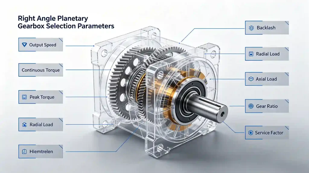
Define these four output parameters before touching a gearbox catalog:
- Required output speed — what RPM does the driven load need? This is usually determined by the machine function: a conveyor belt speed, a rotary table indexing rate, a feed axis velocity.
- Required continuous output torque — the torque the gearbox must sustain during normal operation. This is not the motor torque. It’s the actual load torque at the output shaft, accounting for load weight, friction, inertia during acceleration, and any process forces.
- Required peak output torque — the maximum torque during acceleration, braking, or load spikes. Servo systems often see peak torques 2–3× the continuous value during hard acceleration profiles.
- Required backlash — how much angular play at the output is acceptable? This is determined by the application’s positioning accuracy requirement, not by a general preference for “low backlash.”
With these four values established, you have the gearbox output specification. Everything else follows from here.
Step 2: Determine the Gear Ratio
The reduction ratio connects your motor’s operating speed to the required output speed:
Ratio = Motor Speed (RPM) ÷ Required Output Speed (RPM)
For example: a servo motor rated at 3,000 RPM driving an output shaft that needs to run at 150 RPM requires a ratio of 20:1.
A few practical points about ratio selection:
- Gearbox ratios come in discrete steps—3, 4, 5, 7, 8, 10, 12, 16, 20, 25, 32, 40, 50, and so on, depending on the product line. You won’t always find an exact match. Choose the nearest standard ratio and recalculate the actual output speed to confirm it’s still acceptable for the application.
- Higher ratios reduce reflected load inertia by the square of the ratio, which helps servo inertia matching. But higher ratios also mean the output shaft turns more slowly for the same motor speed—confirm the output speed is still within acceptable limits for the driven component.
- Two-stage right angle planetary gearboxes are typically available for ratios above 10:1. Single-stage units cover approximately 3:1 to 10:1.
- Don’t round up to a much higher ratio “to be safe.” A 40:1 gearbox where 20:1 would do the job gives you an output shaft turning at half the intended speed. The ratio must actually match the application.
Step 3: Calculate Required Output Torque and Apply a Service Factor
Once the ratio is selected, verify the gearbox can handle the torque. The rated torque of the gearbox must exceed the required output torque—but you shouldn’t compare them directly without accounting for the service factor.
The service factor (sometimes called the application factor) accounts for real-world operating conditions that cause higher-than-calculated loads. Impact loads, vibration, non-uniform loading, start-stop frequency, and duty cycle all increase the effective torque demand on the gearbox beyond the theoretical calculated value.
Effective Required Torque = Calculated Output Torque × Service Factor
Service factor values vary by application type. Smooth, uniform loads might use 1.0–1.25. Moderate shock loads typically use 1.5–2.0. Heavy shock or reversing loads can reach 2.0–2.5 or higher. The gearbox manufacturer’s documentation or an industry standard (such as AGMA service factor tables) should be consulted for your specific application type.
The gearbox rated torque must exceed the effective required torque after the service factor is applied. If it doesn’t, move up to the next frame size or ratio option.
Also check the peak torque separately. The gearbox peak torque rating must exceed the maximum instantaneous torque the application will see—servo motor peak current multiplied by the motor torque constant multiplied by the gear ratio, minus efficiency losses. Peak torque spikes that exceed the gearbox rating, even briefly, can cause fatigue damage to gear teeth and bearings over time.
Step 4: Check Radial and Axial Loads
This step is where many engineers make errors. The gearbox output shaft is supported by bearings, and those bearings have load ratings. If your application applies radial or axial forces to the output shaft that exceed the bearing capacity, the gearbox will fail at the bearings long before the gear teeth wear out.
Radial load is any force applied perpendicular to the output shaft axis. Common sources: sprockets, pulleys, timing belt drives, external pinion gears, or any off-center load. To calculate radial force from a torque transmission:
Radial Force (N) = (2 × Torque) ÷ Pitch Diameter of Sprocket or Pulley (m)
Compare this to the gearbox’s rated radial load at the shaft extension point specified in the datasheet. Radial load ratings are typically given at a specific distance from the output shaft bearing face—if your sprocket is mounted further out on the shaft, the effective radial load on the bearing increases. Check the manufacturer’s shaft loading diagram carefully.
Axial load is force applied along the output shaft axis. Helical gears, screw drives, and certain cam mechanisms generate axial forces. Compare your calculated axial force to the gearbox’s rated axial load.
If either load exceeds the rating, you have two options: select a larger frame size with higher load ratings, or redesign the output coupling arrangement to reduce the load (for example, using a flexible coupling to reduce radial force from a misaligned belt drive).
Step 5: Verify Inertia Matching for Servo Applications
This step applies specifically to servo motor drive systems. If you’re driving with an AC induction motor and the speed is controlled by a VFD with no position feedback, skip to Step 6. For servo closed-loop positioning systems, inertia matching is critical.
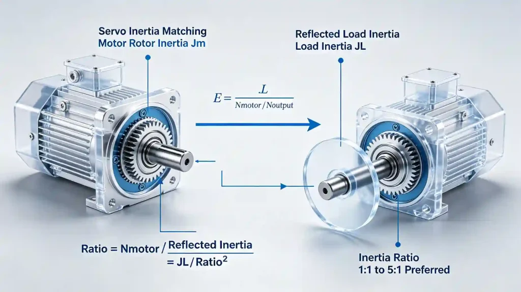
The servo motor’s job is to accelerate and decelerate the load precisely. The load’s inertia, as seen from the motor shaft, determines how much torque is required for a given acceleration rate. The planetary gearbox reduces reflected load inertia by the square of the ratio:
Reflected Load Inertia = Load Inertia ÷ Ratio²
The ratio of reflected load inertia to motor rotor inertia is the inertia ratio. For most servo applications, an inertia ratio between 1:1 and 5:1 is preferred. Some servo drives can handle up to 10:1 depending on the application’s acceleration requirements and the servo tuning. Above that, servo performance typically degrades—the motor struggles to control the load accurately during rapid direction changes.
If the inertia ratio is too high, increasing the gear ratio reduces reflected load inertia by the square of the ratio change—a ratio increase from 5:1 to 10:1 reduces reflected load inertia by a factor of 4. This is often the primary reason for selecting a higher ratio than the speed requirement alone would suggest.
If the inertia ratio is too low—very light load, very large motor—the motor can overshoot. This is less common but worth checking in systems with unusually light loads relative to the motor size.
Step 6: Select the Backlash Class
Right angle planetary gearboxes are available in multiple backlash grades. Selecting the right one matters for cost and performance. Over-specifying backlash adds cost without improving application performance. Under-specifying causes positioning error.
| Backlash Class | Typical Range | Suitable Applications |
|---|---|---|
| Standard | 8–15 arc-min | General automation, conveyors, material handling |
| Reduced | 5–8 arc-min | Packaging machinery, light positioning systems |
| Precision | 3–5 arc-min | Indexing systems, assembly automation, robotics |
| High Precision | ≤3 arc-min | CNC axes, advanced robotics, optical equipment |
| Ultra Precision | ≤1 arc-min | High-accuracy positioning, metrology, semiconductor |
Backlash grades vary by manufacturer—confirm the exact specification in the product datasheet rather than relying on category names alone. Also note that backlash increases over time as gears wear. For long-life applications, it may be worth selecting one grade tighter than the minimum required at installation to allow for wear margin.
Step 7: Confirm the Motor Interface
Right angle planetary gearboxes for servo applications have standardized motor input flanges. Most manufacturers offer multiple input adapter configurations to accommodate different servo motor shaft diameters and bolt patterns.
You need to confirm three things:
- Input flange pattern — does the gearbox offer an adapter for your specific servo motor brand and frame size? Common servo motor frame sizes (IEC 63, 80, 90, 100, 112 and NEMA equivalents) are widely supported. Non-standard motors may require custom adapters.
- Input shaft diameter and coupling method — most servo gearboxes use a clamp-type or keyless coupling at the input to accommodate motor shaft diameter tolerances and allow precise concentricity. Confirm the coupling is compatible with your motor shaft diameter and that the clamping torque capacity is adequate.
- Rated input speed — the gearbox has a maximum input speed rating. Confirm your servo motor’s maximum speed does not exceed this. At high input speeds, bearing wear and heat generation increase. Many right angle planetary gearboxes are rated for input speeds of 3,000–6,000 RPM depending on frame size and design.
Step 8: Select the Output Configuration
Three output configurations are typically available:
- Keyed output shaft — the standard configuration. Connects to a coupling, sprocket, pulley, or pinion via a parallel key and keyway. Widely compatible with standard driven components.
- Output flange — a precision-machined flange face on the output housing. The driven component bolts directly to the flange. Provides higher moment load capacity and better concentricity than a shaft connection for direct-mounted loads.
- Hollow shaft — the driven shaft passes through the gearbox output rather than connecting to it with a coupling. Eliminates one coupling in the drivetrain, reduces total assembly length, and removes a source of alignment error and backlash.
This is a design decision made at ordering—output configurations are generally not interchangeable after manufacture. Choose based on how the gearbox integrates with the driven machine component.
Step 9: Confirm Mounting Orientation and Lubrication
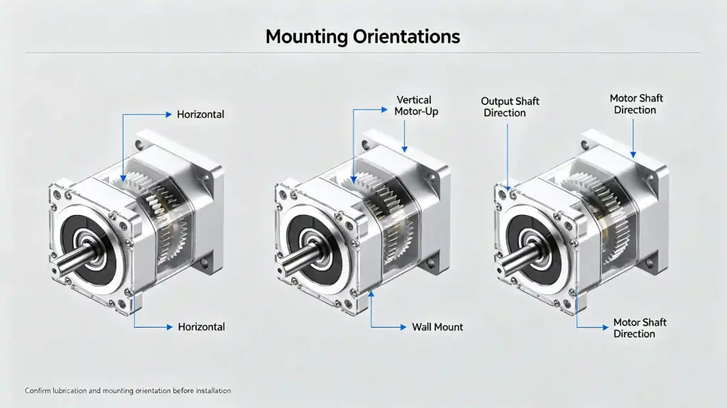
Most right angle planetary gearboxes support multiple mounting orientations—horizontal, vertical motor-up, vertical motor-down, wall-mount. However, lubrication requirements may change with orientation.
Grease-lubricated (lifetime-lubricated) units are generally orientation-independent. Oil-lubricated units may require the breather plug and drain plug to be repositioned when the mounting orientation changes from the default. Confirm with the manufacturer’s installation drawing that the intended mounting orientation is supported and note any lubrication adjustments required.
Also confirm that the output shaft orientation relative to the motor shaft is correct for your machine layout. In most right angle planetary gearboxes, the output shaft is fixed relative to the housing—you cannot rotate the output direction independently. Verify the gearbox geometry fits your machine before ordering.
Common Selection Mistakes to Avoid
Sizing only for ratio and rated torque. Backlash, radial load, and inertia matching are equally important. A gearbox that meets the torque spec but has inadequate radial load capacity fails at the output bearing. One that meets the torque spec but has poor inertia matching causes servo instability.
Ignoring the service factor. Calculating required output torque and comparing it directly to rated torque without applying a service factor leads to undersized selections. Real machines don’t run at perfectly smooth, uniform loads.
Choosing the smallest possible unit. Running a gearbox at 95–100% of its rated torque continuously leaves no margin for load variations, temperature effects, or wear. For long service life, operating at 70–80% of rated torque is a reasonable target in demanding applications.
Forgetting about peak torque. The continuous torque rating is not the only limit. Gear teeth and bearings can be damaged by peak torques that exceed the gearbox’s transient peak rating, even if average loading is within spec. Check both.
Assuming the motor flange fits. Motor adapter availability varies by gearbox manufacturer and frame size. Confirm the specific servo motor model is supported before specifying the gearbox.
Not specifying output configuration at order. Shaft, flange, and hollow shaft outputs are not interchangeable. Decide before you order. Changing this after manufacture typically means a new unit.
Selection Summary Checklist
- ☐ Required output speed defined (RPM)
- ☐ Continuous output torque calculated (Nm)
- ☐ Peak output torque identified (Nm)
- ☐ Backlash requirement defined (arc-min)
- ☐ Gear ratio calculated and standard ratio confirmed
- ☐ Service factor applied to continuous torque
- ☐ Gearbox rated torque ≥ effective required torque
- ☐ Gearbox peak torque rating ≥ application peak torque
- ☐ Radial load at output shaft calculated and compared to rated value
- ☐ Axial load checked against rated value
- ☐ Reflected load inertia calculated (servo applications)
- ☐ Inertia ratio confirmed within acceptable range
- ☐ Motor input adapter confirmed for specific servo motor model
- ☐ Input speed within gearbox rated maximum
- ☐ Output configuration specified (shaft / flange / hollow shaft)
- ☐ Mounting orientation confirmed and lubrication requirements noted
- ☐ Installation envelope dimensions verified
Frequently Asked Questions
What is the most common mistake when selecting a right angle planetary gearbox?
Sizing only for torque and ratio while ignoring radial load at the output shaft. A gearbox driving a sprocket or timing pulley can see significant radial force. If that force exceeds the output bearing rating, the bearing fails—often long before the gear teeth show any wear. Always calculate radial load as a separate check.
How do I know what service factor to apply?
Service factors depend on application type, load uniformity, shock level, and daily operating hours. Most gearbox manufacturers publish application factor tables in their catalogs. As a general starting point: smooth uniform loads use 1.0–1.25, moderate shock uses 1.5–2.0, heavy shock or reversing loads use 2.0–2.5. When in doubt, err on the conservative side—an oversized gearbox costs more upfront; an undersized one costs more over its service life.
Does backlash increase over time?
Yes. As gear teeth wear, clearance increases and effective backlash grows. The rate depends on load, duty cycle, lubrication quality, and operating temperature. For long-life applications with tight positioning requirements, selecting one backlash grade tighter than strictly necessary at installation provides a wear margin that extends the period before re-shimming or replacement is needed.
Can I use the same gearbox for different servo motors?
Only if both motors have compatible input flange patterns and shaft diameters. Motor adapters are typically model-specific. Changing to a different servo motor brand or frame size usually requires a different input adapter—confirm availability with the supplier before planning a motor swap on an existing gearbox installation.
What information do I need to request a gearbox quote?
At minimum: motor make, model, power, and rated speed; required output speed; continuous and peak output torque; required backlash; radial and axial loads; duty cycle; mounting orientation; output configuration preference; and available installation envelope. For replacement projects, the existing gearbox nameplate data is extremely useful for confirming frame size and interface compatibility.
Is a higher ratio always better for servo inertia matching?
Not always. A higher ratio reduces reflected load inertia (which helps inertia matching) but also reduces output speed for the same motor speed. If the higher ratio gives you an output speed that’s too low for the application, you’ve traded one problem for another. Inertia matching and speed requirement must both be satisfied simultaneously—the ratio selection is the balance point between them.
Need Selection Support for Your Application?
If you’re working through a right angle planetary gearbox selection and want a second opinion on the calculation, or if you need help identifying the right unit for a replacement project, send us the application data. Working through an actual selection with real numbers is usually faster than going back and forth on catalog specifications.
EPG Canada Sales Representative Co., Ltd provides gearbox selection support and technical coordination for Canadian OEMs and industrial equipment manufacturers across North America.
Email: [email protected]
Phone: +1-604 719 2870
Address: 10891 Hogarth Dr, Richmond, BC V7E 3Z9, Canada
Send us:
- Servo or motor manufacturer, model, power (kW or HP), and rated speed (RPM)
- Required output speed (RPM) and reduction ratio
- Continuous and peak output torque (Nm or lb-ft)
- Required backlash class (arc-min)
- Radial and axial loads at the output shaft
- Load inertia (for servo inertia matching)
- Duty cycle, daily operating hours, and application type
- Mounting orientation
- Output configuration preference (keyed shaft / flange / hollow shaft)
- Available installation envelope dimensions
- Existing gearbox nameplate data for replacement projects
See the full planetary gearbox range or go directly to the right angle planetary gearbox series. Submit an inquiry here and we’ll work through the selection with you.