
The WP Series worm gearbox is EPG Canada’s heavy-duty cast iron worm reducer line — built for sustained high-torque operation in demanding plant environments where duty cycles are long, shock loads are common, and replacement downtime is expensive. Unlike compact aluminum-housing reducers optimized for light-to-medium duty, the WP Series is engineered to absorb vibration, handle overloads, and run continuously across a full range of frame sizes from 40 to 250.
This page covers WP Series model codes, frame sizes, torque and power ratings, standard gear ratios, material specifications, and mounting configurations. For application-specific guidance on conveyors, mining equipment, and industrial drives, see our WP Worm Gearbox Industrial Applications guide.
WP Series Model Codes: Understanding the Designation System
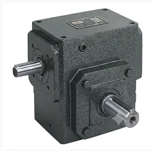
WP Series cast iron worm gearbox — multiple sub-models cover every mounting and shaft configuration
The WP designation covers a matrix of sub-models, each engineered for a specific mounting geometry or shaft configuration. Understanding the model code structure allows procurement teams to specify the exact unit needed without ambiguity:
| Model Code | Full Name | Mounting / Shaft Configuration | Typical Use |
|---|---|---|---|
| WPA | WP Standard — Foot Mounted | Foot (base-plate) mounted; single solid output shaft; hollow input for motor coupling | Floor-mounted drives; most common WP variant |
| WPS | WP Solid Input Shaft | Foot mounted; solid projecting input shaft for chain, belt, or direct coupling | Belt-input and chain-drive arrangements; non-motor inputs |
| WPDA | WP Double Output Shaft | Foot mounted; output shafts on both sides of the housing; hollow motor input | Driving two separate loads from one gearbox; symmetrical conveyor drives |
| WPDS | WP Double Shaft — Solid Input | Foot mounted; double output shafts; solid projecting input shaft | Twin-output drives with non-standard motor input (e.g., hydraulic motor) |
| WPO | WP Hollow Output Bore | Foot mounted; hollow bore on the output for direct shaft mounting; eliminates coupling | Shaft-mounted conveyor and agitator drives; space-saving installations |
| WPWKO | WP Overhead / Suspended | Flange or bracket mounting for overhead / suspended installation; hollow output | Overhead conveyor drives; elevated agitator drives; crane auxiliary drives |
| WPX | WP Extended Housing | Extended housing to accommodate longer shaft or wider bearing span for high overhung loads | High overhung-load applications; screw and auger drives with extended shaft |
Model code example: WPDA-80-40:1 denotes a WP Series, double-output-shaft gearbox (WPDA), frame size 80, ratio 40:1. When ordering, also specify the motor frame size and mounting orientation so the correct motor adapter and oil-fill position are confirmed before shipment.
WP Series Frame Sizes, Torque and Power Ratings
The frame size number indicates the worm center distance in millimetres. The WP Series spans 12 frame sizes from 40 to 250, covering input powers from 0.12 kW to 35 kW and output torques up to 4,500 Nm — one of the broadest single-series worm gearbox ranges available from a single source.
| Frame Size | Centre Distance (mm) | Max Output Torque (Nm) | Input Power Range (kW) | Output Shaft Dia. (mm) |
|---|---|---|---|---|
| 40 | 40 | 30 | 0.12 – 0.55 | 20 |
| 50 | 50 | 60 | 0.18 – 0.75 | 25 |
| 60 | 60 | 105 | 0.37 – 1.1 | 30 |
| 70 | 70 | 170 | 0.55 – 1.5 | 35 |
| 80 | 80 | 260 | 0.75 – 2.2 | 40 |
| 100 | 100 | 460 | 1.5 – 4.0 | 50 |
| 120 | 120 | 760 | 2.2 – 7.5 | 60 |
| 135 | 135 | 1,050 | 3.0 – 11 | 70 |
| 155 | 155 | 1,580 | 4.0 – 15 | 80 |
| 175 | 175 | 2,150 | 5.5 – 22 | 90 |
| 200 | 200 | 2,850 | 7.5 – 30 | 100 |
| 250 | 250 | 4,500 | 11 – 35+ | 120 |
* Max output torque values are at lowest efficiency. Always apply a service factor (SF) before selecting frame size — typical SF: 1.25 for moderate shock, 1.5–2.0 for heavy shock or 24/7 duty. Contact our team for thermal power ratings on continuous-duty applications.
Standard Gear Ratios: Single Stage and Double Stage
Single Stage — Ratios 5:1 to 100:1
| Ratio | Output RPM (1,450 in) | Efficiency (approx.) |
|---|---|---|
| 5:1 | 290 | ~85–90% |
| 10:1 | 145 | ~80–85% |
| 15:1 | 97 | ~77–82% |
| 20:1 | 72 | ~74–80% |
| 30:1 | 48 | ~70–76% |
| 40:1 | 36 | ~68–74% |
| 50:1 | 29 | ~66–72% |
| 60:1 | 24 | ~64–70% |
| 80:1 | 18 | ~62–68% |
| 100:1 | 14.5 | ~60–66% |
Double Stage — Ratios 200:1 to 900:1
| Combined Ratio | Stage 1 × Stage 2 | Output RPM (1,450 in) |
|---|---|---|
| 200:1 | 20 × 10 | 7.3 |
| 300:1 | 30 × 10 | 4.8 |
| 400:1 | 20 × 20 | 3.6 |
| 600:1 | 30 × 20 | 2.4 |
| 900:1 | 30 × 30 | 1.6 |
Important: Dual-stage WP efficiency is the product of both stages — at 30×30 (900:1), overall efficiency may be as low as 42–49%. Always size the motor for thermal power loss, not just mechanical output torque, when using double-stage configurations.
* Available ratio steps may vary by frame size. Confirm exact ratio availability for your frame size before ordering. Custom ratios are available through the Non-Standard program.
Why Cast Iron Housing: The Technical Case for Heavy-Duty Applications
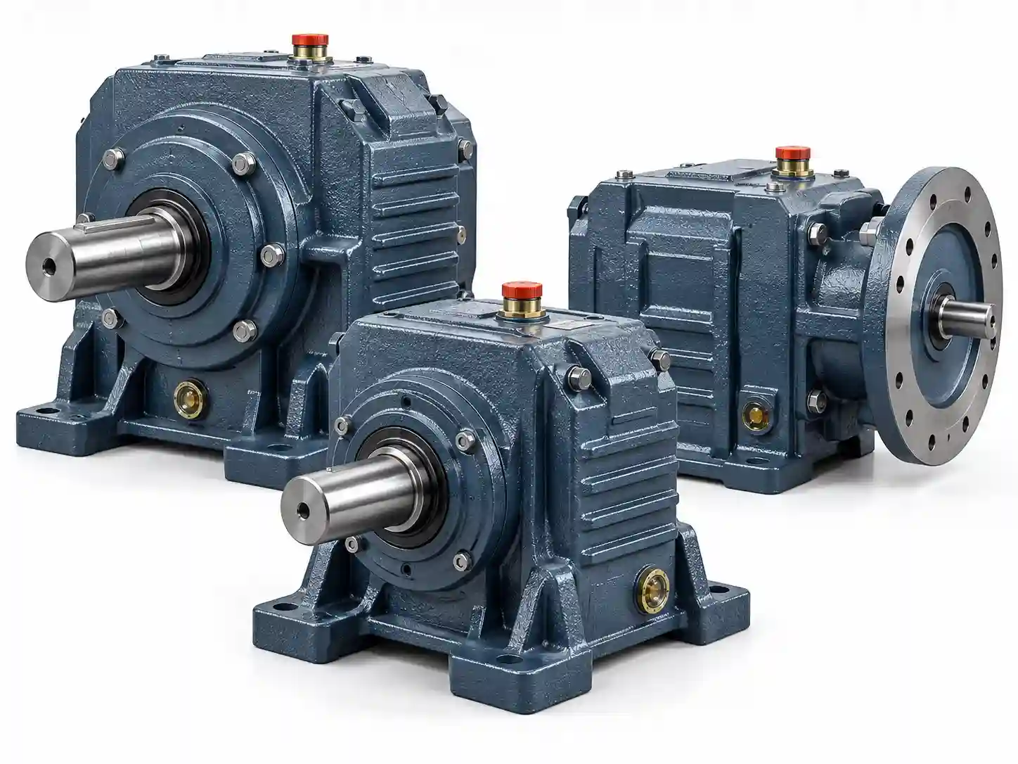
The WP Series uses heavy-duty cast iron (grey iron GG25 / HT250 grade) throughout all frame sizes — not just on larger units. This is a deliberate engineering decision driven by the application profile the WP Series is designed for, not a cost default. Cast iron delivers four specific advantages in sustained high-torque industrial service:
Superior Structural Rigidity
Cast iron’s higher elastic modulus maintains housing geometry under large worm reaction forces, preventing bearing misalignment and premature gear wear on heavily loaded drives.
High Vibration Damping
Cast iron absorbs vibration energy far more effectively than aluminum. On applications with repeated shock loads — conveyors starting under load, stone crushers, material handling — this damping capacity directly extends gear pair and bearing service life.
Thermal Mass for Sustained Duty
Cast iron’s high thermal mass acts as a heat buffer during sustained continuous operation, smoothing out temperature spikes from load surges before they affect lubricant viscosity and film strength.
Breather Plug & Oil Mirror
All WP Series units include a breather plug to equalize internal pressure during thermal cycling, and an oil sight glass to allow visual oil level inspection without draining — reducing maintenance time and the risk of running under-oiled.
Worm Shaft and Worm Wheel Material Specifications
Worm Shaft (Input)
- Material: 45# high-quality carbon steel (or 20CrMnTi alloy on larger frames)
- Heat treatment: Through-hardening and quenching
- Surface finish: Precision ground worm threads
- Thread profile: Hollow flank worm — increases contact ratio with the worm wheel
- Hardness: 45–55 HRC (surface)
Worm Wheel (Output)
- Rim material: Tin (stannum) bronze alloy — Cu-Sn-10-3
- Manufacturing: Centrifugally cast bronze rim onto a cast iron hub
- Hub: Cast iron (GG25) for higher strength at large frame sizes
- Tooth profile: Machined to national standard GB/T 16444
- Worm/wheel pair meets precision grade 8 minimum
Bearing specification: The output shaft on all WP Series frame sizes runs on tapered roller bearings, selected for their combined radial and thrust load capacity — essential given the axial force generated by the worm gear geometry. The input shaft bearings are matched to the frame size’s input speed and radial load conditions. All bearing fits are precision-machined to maintain alignment under full operating load.
Mounting Positions and Installation Flexibility
WP Series gearboxes support omnidirectional mounting. The housing is sized to maintain adequate oil coverage of the worm gear pair in any mounting orientation, provided the correct oil quantity for that orientation is used. Standard mounting positions include:
| Mounting Position | Description | Oil Fill Adjustment Required? |
|---|---|---|
| B3 / Horizontal | Standard foot-down, output shaft horizontal — the most common WP installation | No (standard fill) |
| V5 / Vertical shaft-up | Output shaft pointing upward; motor below housing | Yes — confirm fill level |
| V6 / Vertical shaft-down | Output shaft pointing downward; motor above housing | Yes — confirm fill level |
| Wall-mounted | Housing bolted to vertical structure; input shaft horizontal or vertical | Yes — confirm orientation |
| Overhead (WPWKO) | Suspended from structure above; output shaft downward | Yes — use WPWKO model |
Single Stage vs Double Stage: Selecting the Right Configuration
Single Stage WP Gearbox
- Ratio range: 5:1 to 100:1
- Higher efficiency (60–90% depending on ratio)
- Compact axial length — fits tighter spaces
- Lower heat generation for the same input power
- Choose when ratio requirement is ≤100:1
Double Stage WP Gearbox
- Ratio range: 200:1 to 900:1
- Lower combined efficiency (40–60%)
- Larger overall envelope — plan installation space
- Higher thermal load — verify thermal rating carefully
- Choose when very low output speed is required (e.g., rotating kiln, slow agitator, rack-and-pinion gate)
Request WP Series Technical Data Sheet or Quotation
Provide your model code, frame size, ratio, and mounting orientation. We will return a confirmed dimensional drawing, oil specification, and pricing within 24 hours.