Descripción
The Frame Support Cylinder: Why Every Crawler Crane Lift Starts at Ground Level
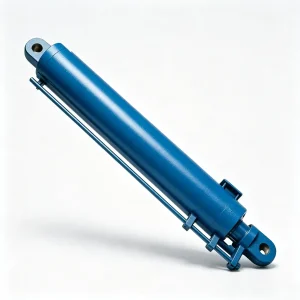
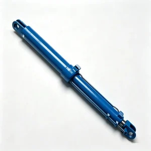
Before the boom goes up, before the hook comes out, before any load leaves the ground — the crawler crane frame support hydraulic cylinder has already done its job. The HCYY11112020 is the undercarriage stabilizer that sets the crane’s main frame to a precise level position on uneven or soft ground, creating the geometric foundation that every load chart calculation assumes is in place when the crane starts lifting.
This is a shorter, lower-stroke cylinder than the boom hoist or anti-tip units — 800 mm of travel from a 1140 mm installation distance — but what it lacks in reach it makes up for in load density. At Φ170 mm bore and 30 MPa, the crane leveling cylinder generates approximately 681 kN of force. It transmits that force directly into the crawler frame structure, bearing a share of the crane’s total weight plus lifted load while the machine is stationary on the pads. Unlike the boom cylinders, which cycle with every lift, the frame support cylinder is loaded continuously for the entire duration of the job — sometimes days at a time on large infrastructure projects.
The HCYY11112020 also has the most extreme bore-to-rod ratio in this cylinder set: Φ170 bore with a Φ150 rod — a ratio of just 1.13:1. That near-equal sizing tells you immediately that this cylinder is designed to take compression load in both directions. Whether the frame is being pushed down against the ground or being pulled up as the frame flexes under lift load, the rod section needs to be stiff enough in both modes to prevent column buckling and maintain precise frame geometry.
Technical Specifications — HCYY11112020 Frame Support Hydraulic Cylinder
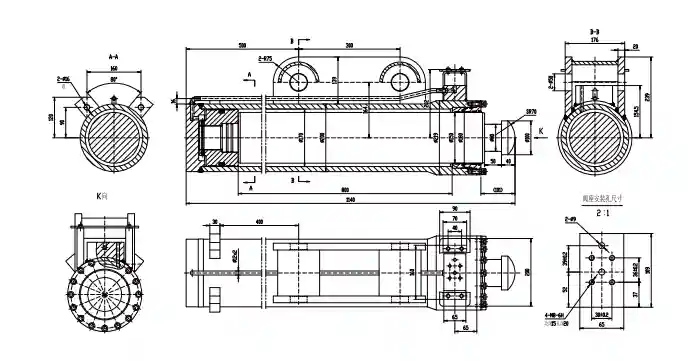
| Parameter | Value | Engineering Context |
|---|---|---|
| Model | HCYY11112020 | Crawler crane undercarriage frame support series |
| Bore × Rod × Stroke | Φ170 × Φ150 × 800 mm | 1.13:1 bore-to-rod ratio — tightest of the three crane cylinders; designed for bidirectional compressive rigidity |
| Working Pressure | 30 MPa | Push force ≈ 681 kN; pull force ≈ 504 kN at rated pressure |
| Max Withstand Pressure | 40 MPa | 33% safety margin — highest ratio of the three crane cylinders |
| Stroke (Trip) | 800 mm | Covers typical site ground irregularity compensation range |
| Installation Distance | 1140 mm | Compact retracted length fits within the crawler undercarriage frame depth |
| Weight | 262 kg | Lightest of the three crane cylinders; fits within undercarriage maintenance access envelope |
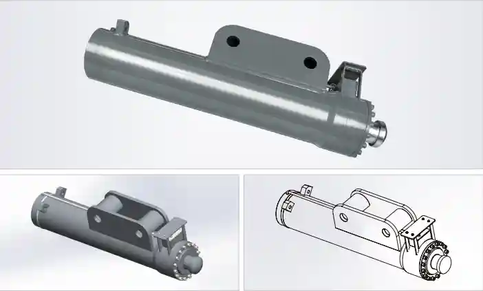
Why the Frame Support Cylinder Has the Highest Pressure Safety Margin of the Three — and What That Tells You
The HCYY11112020 operates at 30 MPa working pressure — slightly lower than the 31.5 MPa of the boom cylinders — yet it shares the same 40 MPa withstand rating. That gives it a 33% safety margin, compared to 27% on the other two. This is not accidental over-engineering. It reflects the specific load character of the frame support position.
A frame support cylinder on a crawler crane is subject to ground-transmitted shock loads that the boom cylinders simply don’t see. When the crane travels over uneven terrain with the frame supported on these cylinders, every bump, rut, and obstacle translates into a vertical impulse directly into the cylinder. On soft ground — clay, saturated fill, or prepared crane mats that compress unevenly — the cylinder load can shift suddenly as the mat yields in one corner while the others hold. These dynamic ground-reaction events generate pressure spikes that are faster, shorter, and potentially higher than anything seen in the controlled luffing or anti-tip circuits. The 10 MPa margin above working pressure is the buffer that absorbs those spikes without triggering the relief valve — which, if it fired during a lift, would allow the frame to shift and the boom geometry to change instantaneously.
The 1.13:1 bore-to-rod ratio deserves another look here. With a Φ150 rod in a Φ170 bore, the annular area is only 2,749 mm² compared to the cap-end area of 22,698 mm². That makes the retraction force (pull) approximately 504 kN — meaningfully lower than the 681 kN push force. This asymmetry is intentional: the primary load direction is compressive (pushing the frame up against gravity and crane weight), and the cylinder is optimized for that direction. The pull force is sufficient for retraction against gravity alone — it doesn’t need to pull against an opposing load.
The 800 mm stroke accommodates the typical ground level variation encountered on prepared crane pads — roughly equivalent to leveling a 300-tonne crawler crane across a site with up to 400 mm of cross-slope variation at the crawler centerline distance. Beyond that range, site preparation is required before the crane can be deployed safely, regardless of cylinder specification.
Where the Crawler Crane Leveling Cylinder Earns Its Keep
The HCYY11112020 is continuously loaded at every site where the crawler crane operates. The operating environments that stress it most:
- Soft-ground construction sites — where crawler mats are used and consolidation settlement during the lift changes the effective cylinder load distribution between the support points
- Bridge and infrastructure construction — where the crane must be set up on prepared ground adjacent to excavations or embankments, often with a cross-slope that the frame support cylinders must compensate for
- Port and marine construction — where the crane operates on quaysides or barge decks subject to tidal settlement, deck deflection, or wave action that creates continuous low-amplitude dynamic loading
- Power plant and industrial construction — where the crane must be repositioned repeatedly between picks and the frame support cylinders extend and retract dozens of times per shift during a long job
- Cold-climate winter construction — where frozen ground thaws unevenly under the crane mats during a long lift, creating progressive settling that the frame support cylinders must accommodate in real time
Construction Details — Short-Stroke, High-Load, Long-Duration
Cylinder Barrel
Seamless forged steel (27SiMn), thick-wall construction for 40 MPa burst with additional ground-shock load case in the design analysis. Bore honed to Ra ≤ 0.4 μm for low static-friction breakout — critical for precision leveling.
Heavy-Section Rod
Φ150 mm 42CrMo4, hard chrome ≥ 30 μm. The massive rod cross-section (vs. the 800 mm short stroke) gives an extremely favourable slenderness ratio — Euler buckling is not a concern even under eccentric ground reaction loads.
Static Seal Design
Seals optimized for long-duration static loading rather than high-cycle dynamic operation. PU piston seals with PTFE-lined backup rings maintain consistent leak-free performance under sustained pressure hold for 24–72+ hour lift operations.
Foot Pad Interface
Rod end fitted with a spherical-seat steel bearing pad, compatible with standard crane mat and timber cribbing interfaces. Pad diameter and contact pressure engineered to prevent punching through standard crane mat composites.
Load-Holding Valve
Pilot-operated check valve on the cap-end port prevents any frame settlement if the hydraulic supply is isolated or lost during a lift. The frame will not retract regardless of supply pressure — the load is held mechanically by the check valve.
Corrosion Protection
External barrel: epoxy primer + polyurethane topcoat, minimum 100 μm DFT — heavier than the boom cylinders because the frame support cylinder operates in ground contact and is routinely exposed to mud, standing water, and road-salt runoff during transport.
Crawler Crane Hydraulic Cylinder Installation Positions
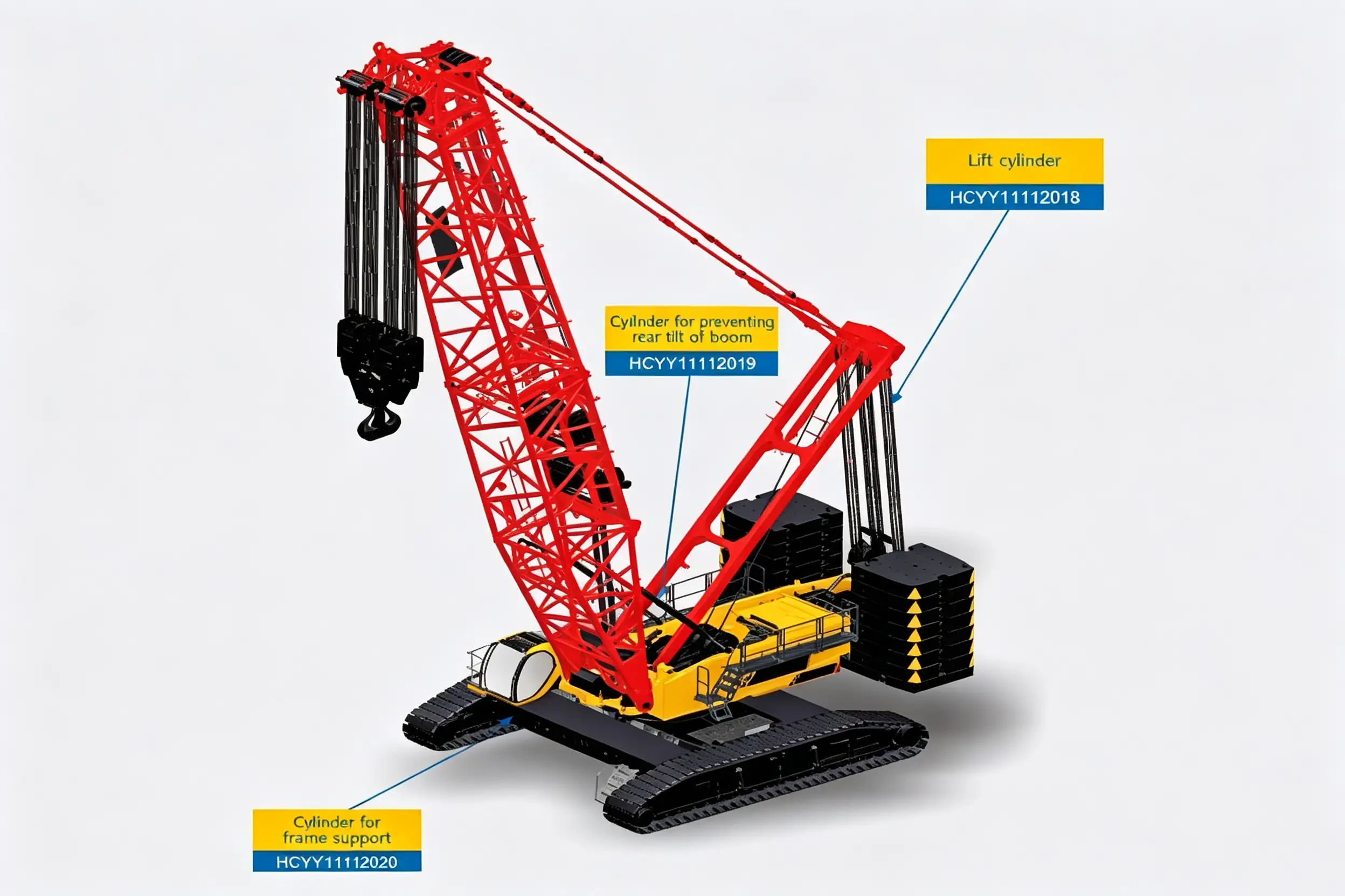
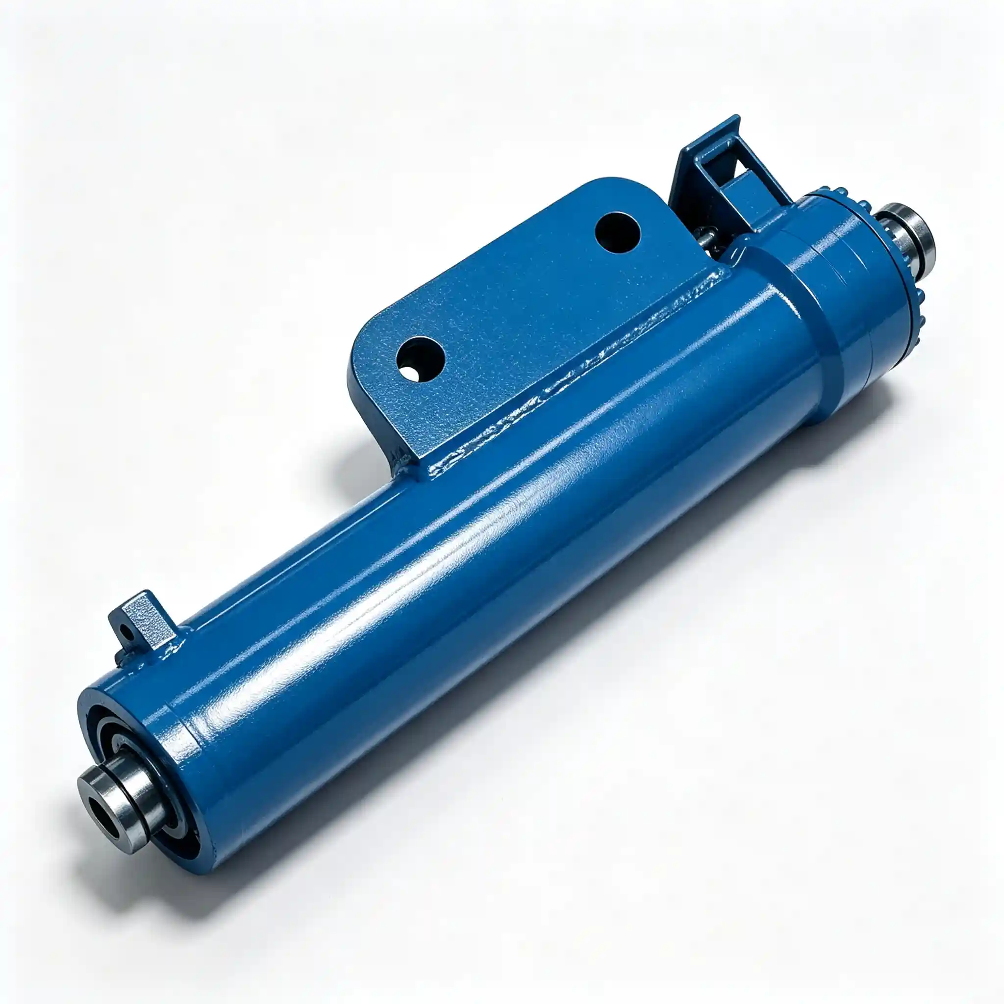
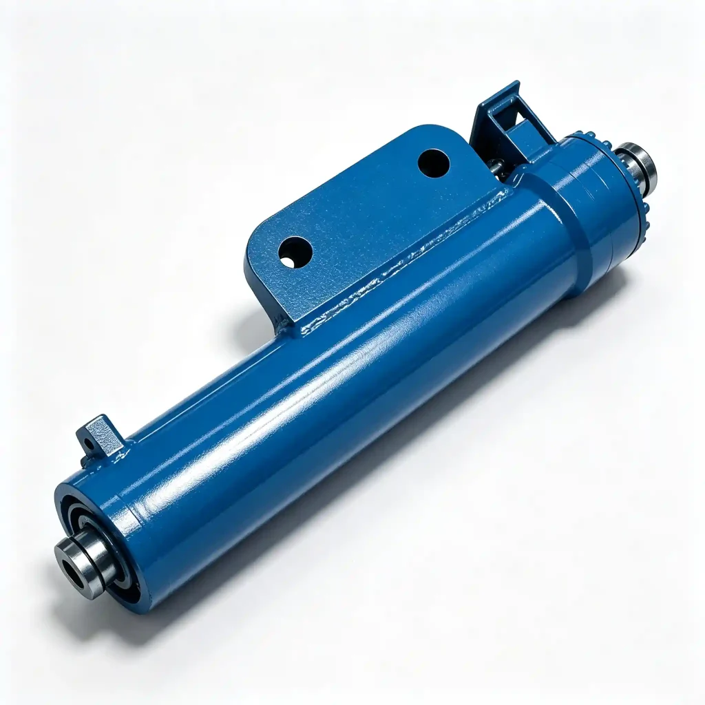
The frame support cylinders sit in the undercarriage structure, extending downward to level the main frame against uneven ground before and during lifting operations.
Installation, Leveling Procedure, and Field Maintenance Notes
At 262 kg, the HCYY11112020 is the most field-serviceable cylinder in the crawler crane system. But “manageable weight” doesn’t mean “casual installation.” Key points:
- Clean the pin bores and contact faces before installation — the undercarriage environment means these cylinders accumulate ground-in debris at the mounting points that can prevent full seating and introduce angular misalignment.
- Level the crane in stages, not all at once. Extend all frame support cylinders to approximately 50% stroke, check the frame level with a precision spirit level or electronic inclinometer, then adjust individual cylinders to achieve level within ±0.1° before committing to the final position. One large adjustment on a single cylinder introduces torsion into the frame structure.
- Verify the load-holding check valve function after installation by isolating the hydraulic supply with the frame fully extended and loaded. The cylinder must show zero settlement over a 10-minute period before the crane proceeds to boom erection.
- Inspect the foot pad spherical seat at each cylinder deployment — debris ingress between the pad and the crane mat causes uneven contact and eccentric loading into the rod that accelerates gland wear.
- Record the extension measurement at each support point as part of the lift plan documentation — this confirms the frame is within the leveling range for the site conditions and provides a baseline for detecting ground settlement during the lift.
Common Questions — Crawler Crane Frame Support Hydraulic Cylinder
Need the HCYY11112020 in a Matched Set — or Custom Configuration?
We supply crawler crane frame support cylinders to OEM crane manufacturers, fleet maintenance operations, and heavy-lift project contractors worldwide. Matched sets of 4, hydrostatic test certificates, dimensional drawings, and seal kits available as standard. Active leveling variants with position feedback and custom foot pad configurations on request.
Model: HCYY11112020 · Φ170×Φ150×800 · 30 MPa / 40 MPa · 800 mm stroke · 1140 mm installation distance · 262 kg