Descripción
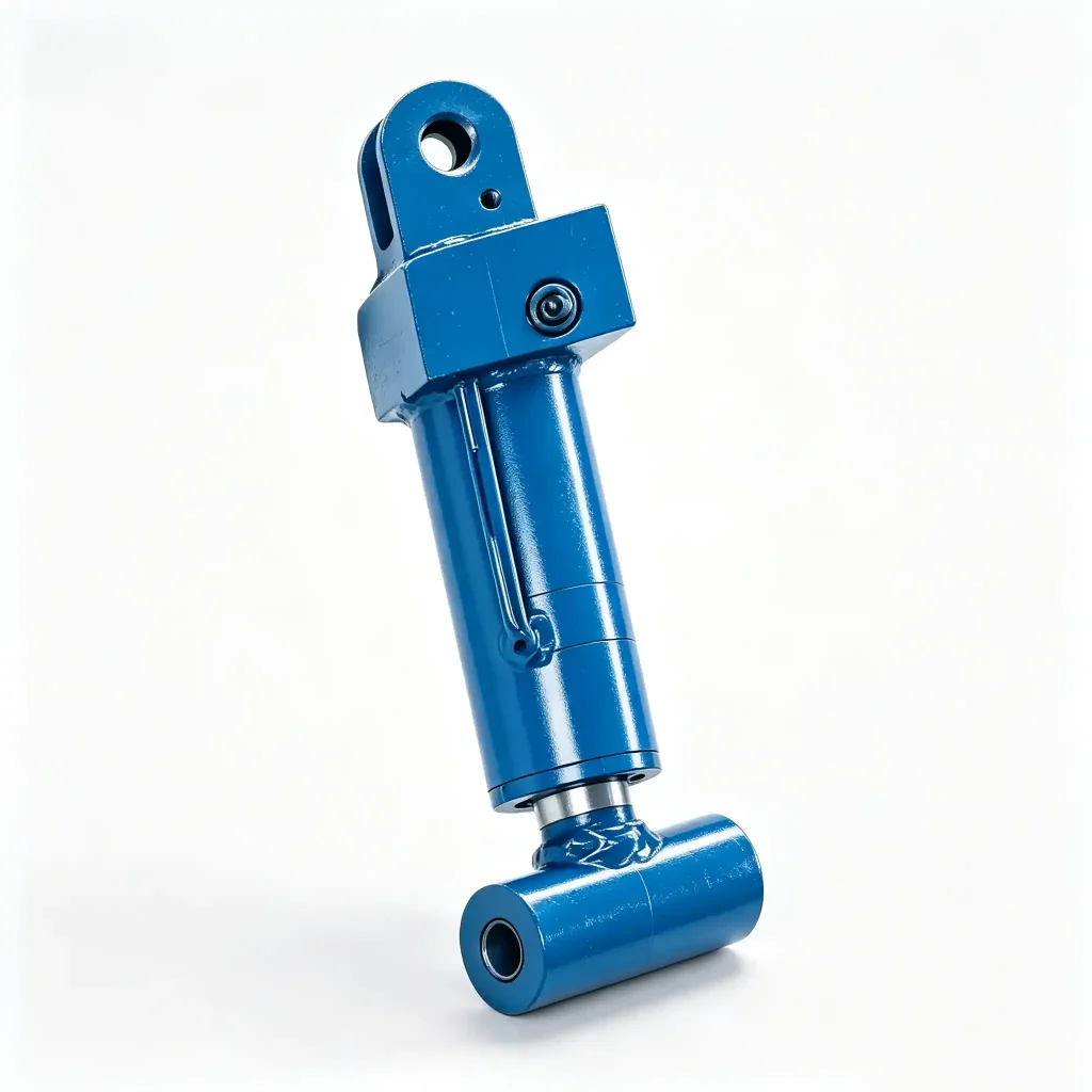
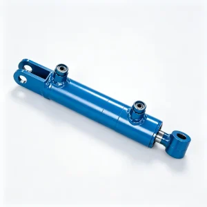
HCYY11112008 — Boom Lift Platform Leveling Hydraulic Cylinder (Upper Leveling Cylinder)
The HCYY11112008 is the upper platform leveling cylinder on a boom-type aerial work platform — the actuator that keeps the work basket horizontal as the boom raises, lowers, and articulates. Its specifications are immediately distinctive: a 60 mm stroke paired with 25 MPa working pressure, making it the shortest-stroke, highest-pressure cylinder in this entire product line.
That combination is not a coincidence. The leveling mechanism on a boom lift is a parallelogram linkage — the cylinder does not need long travel to compensate for boom angle changes, because the linkage geometry amplifies small cylinder movements into full platform angle correction. But it must generate very high holding force in a small envelope, which is why 25 MPa is required where the lifting cylinders on the same machine run at 18 MPa. The Φ63 bore at 25 MPa delivers approximately 78 kN of force through a 375 mm installation distance — enough to hold the platform level under a fully loaded basket at any boom angle, without drift.
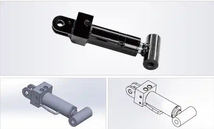
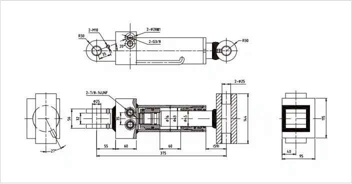
Technical Specifications — 25 MPa Upper Leveling Cylinder, 60 mm Stroke
| Parameter | Value | What It Means in Practice |
|---|---|---|
| Model | HCYY11112008 | OEM part reference for sourcing and cross-referencing |
| Bore × Rod × Stroke | Φ63 × Φ45 × 60 mm | Large rod-to-bore ratio (0.71) — resists the lateral side loads typical in leveling linkage geometry |
| Working Pressure | 25 MPa | Highest in this product range — 39% higher than the 18 MPa lifting cylinders on the same machine |
| Max Withstand Pressure | 30 MPa | Covers dynamic pressure spikes when the boom moves rapidly and the leveling system corrects suddenly |
| Stroke | 60 mm | Shortest stroke in this range — the parallelogram linkage amplifies this 60 mm into full boom-angle compensation |
| Installation Distance | 375 mm | Pin-to-pin retracted length; must match the leveling linkage pivot geometry exactly |
| Weight | 16 kg | Heavier per unit stroke than any other cylinder here — thick wall required at 25 MPa with Φ63 bore |
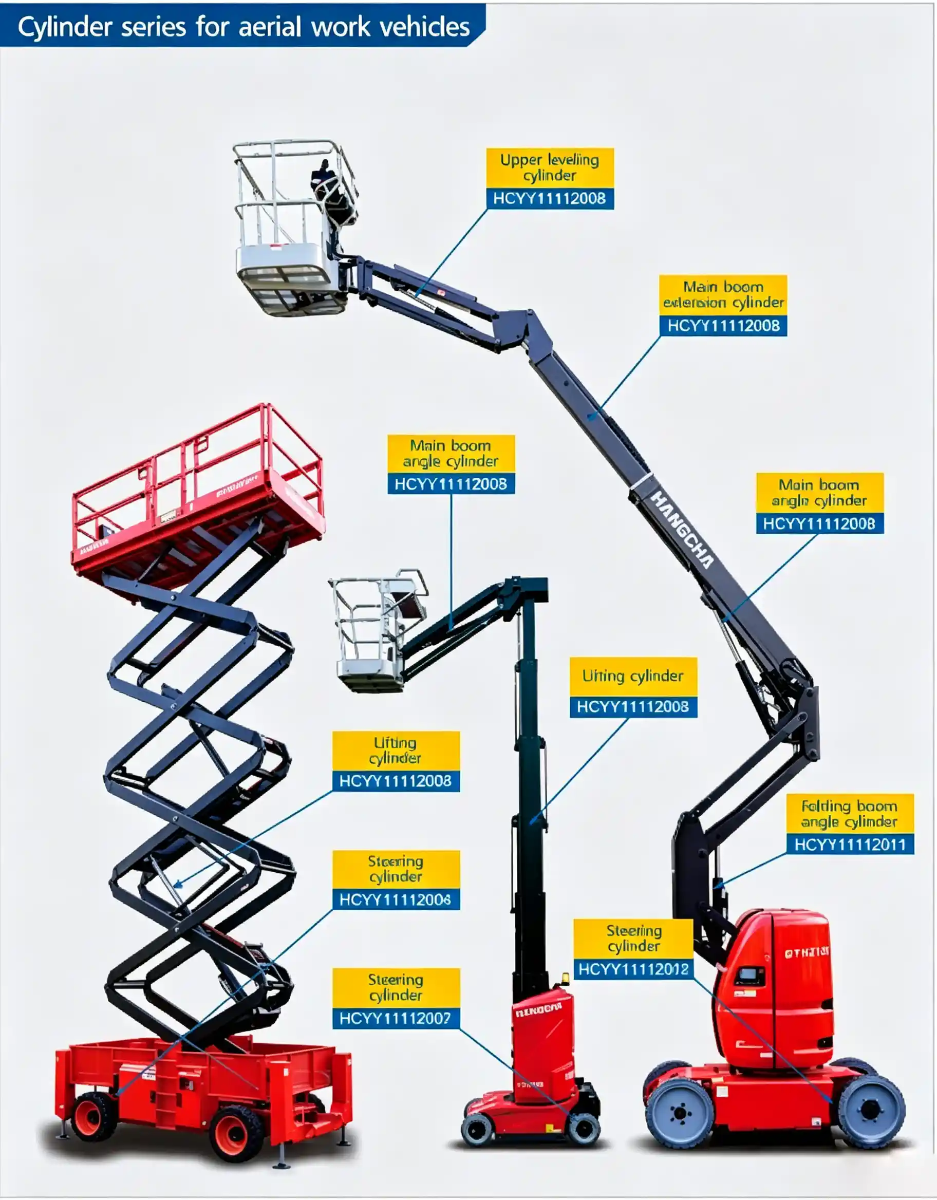
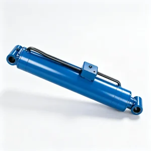
Installation position reference — HCYY11112008 upper leveling cylinder location in the boom lift hydraulic layout
Why a 60 mm Stroke Cylinder Needs 25 MPa: The Mechanics of Boom Lift Platform Leveling
A boom lift platform leveling system works through a parallelogram linkage — typically a four-bar arrangement where the leveling cylinder is one of the moving links. The geometry of this linkage means that a small change in cylinder length (60 mm) produces a large angular correction at the platform pivot. That is exactly the point: the cylinder travels very little, but the moment it holds against is substantial.
Consider what the cylinder is resisting. When a boom lift is elevated to 80° with a 300 kg payload in the basket at the end of a 12-meter boom, the bending moment at the platform pivot is significant. The leveling cylinder must generate enough force through its lever arm in the parallelogram to counteract this moment — and hold it statically, with zero movement, because the control valve is closed and there is no active hydraulic correction happening. The 78 kN force available at 25 MPa through the Φ63 bore is what keeps the platform level in this condition.
Compare this to the main lifting cylinder: it moves the entire boom through 840 mm or more, but it does so against a much more favorable mechanical advantage from the boom pivot geometry. The leveling cylinder has far less mechanical advantage in the parallelogram — hence the higher pressure to compensate.
Zero Internal Bypass: The Non-Negotiable Sealing Standard for Platform Leveling Cylinders
Every hydraulic cylinder has some internal seal bypass — fluid that passes across the piston seal from the high-pressure side to the low-pressure side under load. In a lifting cylinder, a small amount of bypass causes slow, gradual boom settling over time — noticeable but rarely dangerous in practice. In a leveling cylinder, any bypass directly tilts the work platform.
At full boom extension with a loaded basket, platform tilt from a bypassing leveling cylinder is not a slow drift an operator can monitor and correct. It is a fall hazard. This is why EN 280 and ANSI A92.2 require that work platforms remain within ±2° of level during all operating conditions — and why the leveling cylinder is the component that enforces this tolerance when the system is at rest.
The HCYY11112008 is manufactured and tested to a zero-bypass standard: each cylinder is pressurized to working pressure on one side with the opposite port blocked, and held for a defined dwell period. Zero measurable pressure decay is required to pass. There is no allowable bypass figure for this cylinder — not 0.5 cc/min, not 0.1 cc/min. The acceptance criterion is zero drift under static load.
This requirement shapes the manufacturing process: piston seal tolerances are tighter than on standard double-acting cylinders, the bore honing process is held to a tighter Ra finish, and piston-to-bore fit is verified dimensionally before assembly. A cylinder that passes the pressure-burst test but fails the static drift test is rejected — there is no rework path for a leveling cylinder that allows internal bypass.
Φ45 Rod on a Φ63 Bore: Why the High Rod-to-Bore Ratio Matters for Leveling Cylinder Longevity
The Φ45 mm rod on a Φ63 mm bore gives a rod-to-bore ratio of 0.71 — substantially higher than what a pure force calculation would require for a 60 mm stroke at 25 MPa. The reason for this thick rod is not buckling resistance (a 60 mm stroke needs almost no column stability support) — it is side load management.
In a parallelogram leveling linkage, the cylinder is rarely loaded in pure axial tension or compression. As the boom angle changes, the angle between the cylinder axis and the linkage arm shifts — creating a transverse force component on the rod that the rod guide bushing must absorb. A thin rod deflects under this side load and creates uneven contact between the rod and the rod seal, accelerating seal wear on the side under highest contact pressure.
The Φ45 mm rod has substantially higher section modulus than a minimum-design rod for this stroke — which means less deflection under side load, more uniform seal contact, and longer service life between rod seal replacements. For machines in rental fleet service where the boom cycles hundreds of times per day, this directly translates to lower maintenance cost and fewer unscheduled service events.
Leveling Cylinder Duty Cycle: Every Boom Movement Is a Leveling Cylinder Cycle
Unlike the main lifting cylinder — which extends to raise the boom and retracts to lower it, typically once or twice per repositioning move — the leveling cylinder is in continuous active duty every time the boom moves. Every millimeter of boom elevation or retraction requires a corresponding compensation movement from the leveling cylinder to maintain platform horizontal.
On an articulating boom lift used in facility maintenance, an operator might raise and lower the boom 20–30 times in an eight-hour shift as they move between work positions. Each raise-lower cycle puts the leveling cylinder through its full travel range in both directions. Over a 1000-hour annual service year, this means hundreds of thousands of seal cycles — far more than the main lift cylinder accumulates in the same period.
This duty cycle intensity is why the HCYY11112008 uses a premium seal stack: a U-cup rod seal with an anti-extrusion ring rated for 25 MPa continuous duty, backed by a polyurethane rod wiper that excludes contamination on every retraction stroke. The seal materials are selected for compatibility with standard HLP 46 mineral hydraulic oil as well as biodegradable HEES ester fluids for machines operating in environmentally sensitive areas.
How to Identify a Failing Leveling Cylinder Before It Becomes a Safety Issue
Leveling cylinder degradation rarely happens suddenly — it develops progressively, and there are measurable indicators well before the cylinder reaches a safety-critical bypass level. Maintenance teams should watch for:
- Platform slow to level after boom movement stops — if the platform takes more than 1–2 seconds to settle horizontal after the boom control is released, the cylinder may be operating with reduced seal efficiency. This is an early-stage indicator, not an emergency — but it should trigger a static drift test.
- Platform tilt visible at full boom extension under load — if the platform is noticeably off-level when a technician climbs in at maximum boom height, the internal bypass has reached a level that the leveling circuit can no longer passively compensate. Take the machine out of service immediately for cylinder inspection.
- Oil film on the rod that does not clear between cycles — at 25 MPa, the rod seal is under high stress. A wet rod that leaves an oil trace on the wiper seal housing is a sign the rod seal is beginning to weep. At this pressure, a weeping seal can become an active leak within days of first appearing.
- Jerky or inconsistent leveling response — if the platform corrects in small increments rather than smoothly, the piston seal may be experiencing stick-slip due to seal wear or contamination. This also appears as visible platform oscillation during slow boom movements.
Specifying the Correct Replacement Leveling Cylinder: Why Installation Distance Precision Is Critical
The HCYY11112008’s 375 mm installation distance is not a loose reference dimension — it is the geometric constraint that determines the platform’s level position at full boom retraction. The parallelogram leveling linkage is designed around this retracted cylinder length. If a replacement cylinder is even 5 mm longer or shorter in installation distance, the platform will sit at a slight angle in the boom-down transport position — which means it will also be off by the same angle at every elevated position.
On a machine subject to type-testing under EN 280 or ANSI A92 standards, a platform that fails the ±2° level tolerance at any operating position is a non-compliance that must be resolved before the machine returns to service. The installation distance of the replacement cylinder is not a “close enough” dimension.
When ordering, always specify: cylinder model HCYY11112008, or provide your platform model and boom drawing reference so we can confirm the 375 mm installation distance matches your specific leveling linkage geometry before dispatch.
Platform Types and Operating Environments This Cylinder Is Designed For
- Articulating boom lifts with upper and lower boom sections — the upper leveling cylinder sits at the platform pivot, compensating for the combined angular change as both boom sections articulate independently. This is the highest-demand leveling application because two independent motion inputs must be compensated simultaneously.
- Telescopic boom lifts with platform leveling — where a single main boom angle changes and the leveling cylinder provides a proportional compensation. Simpler kinematics, but the same zero-drift sealing requirement applies.
- Truck-mounted aerial platforms — where road vibration and vehicle body flex during transport create additional dynamic loading on the leveling cylinder beyond normal operational cycles.
- High-frequency-use rental fleet machines — platforms cycling 30+ times per day in construction, facilities management, or event rigging applications where leveling cylinder seal life is a key maintenance planning parameter.
- Environmentally sensitive work sites — the HCYY11112008 seal package is available with HEES ester fluid compatibility for machines working near water courses, forests, or other areas where mineral oil spills require mitigation.
Request HCYY11112008 — Zero-Bypass Test Certificate Included
We supply the HCYY11112008 to aerial platform manufacturers, fleet operators, and authorized service centers. Every unit ships with a documented zero-bypass static drift test result and a 30 MPa proof pressure test certificate. We do not ship leveling cylinders without passing both tests.
- Static drift test certificate (zero bypass) per unit
- 30 MPa hydrostatic proof test record
- Dimensional drawing with installation distance verification
- HEES-compatible seal option available on request
- Emergency stock and expedited shipping for out-of-service machines
Submit your RFQ — include platform model, annual volume, and whether you need standard or HEES-compatible seals. We confirm within one business day.