Descripción
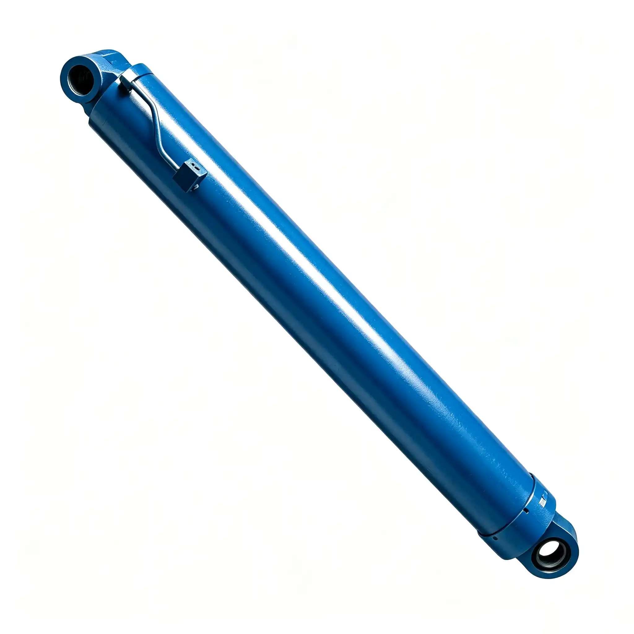
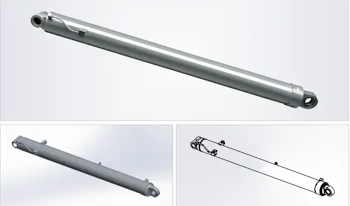
Model: HCYY11112021
Crane Main Boom Lift Hydraulic Cylinder
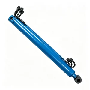
The crane main boom lift hydraulic cylinder HCYY11112021 is the primary actuator responsible for elevating the entire boom assembly of a mobile or truck-mounted crane. With a Φ280mm bore, a 3,507mm stroke, and a rated working pressure of 31.5MPa, this cylinder is built to handle the enormous bending moments and dynamic loads that occur during full-capacity lifts — the operational conditions where component failures carry the highest consequences.
Key Specifications at a Glance
- Bore × Rod × Stroke: Φ280 × Φ250 × 3507 mm
- Working Pressure: 31.5 MPa
- Max Withstand Pressure: 39 MPa
- Installation Distance: 4,218 mm
- Weight: 1,155 kg
What the Heavy-Duty Boom Cylinder Actually Does Inside a Crane
In a mobile crane, the main boom is not a rigid structure — it is a dynamic load arm that pivots at the base and must be raised and held at precise elevation angles under rated load conditions. The main boom lift hydraulic cylinder is the single component that controls that pivot. When a crane is lifting at maximum capacity, the cylinder rod is under combined axial compression and transverse bending force simultaneously. At full extension, it must maintain position without drift — any slow hydraulic leak or seal failure translates directly into uncontrolled boom descent.
The HCYY11112021 is designed to address precisely these conditions. Its Φ250mm rod diameter is not arbitrary — a rod this size has the cross-sectional area and second moment of area needed to resist buckling under the eccentric loads that occur when a boom is angled and loaded asymmetrically. The 3,507mm stroke allows the boom to sweep through a wide elevation arc while the 4,218mm installation distance — measured pin-to-pin at full retraction — accounts for the geometric constraints of typical crane chassis design.
At 1,155 kg, this is a heavy-duty industrial actuator. It is appropriate for truck-mounted cranes, all-terrain cranes, rough-terrain cranes, and crawler cranes in the 25-tonne to 200-tonne capacity range where main boom geometry demands cylinders of this bore class.
Installation Position Diagram — HCYY11112021 / 22 / 23 on Crane
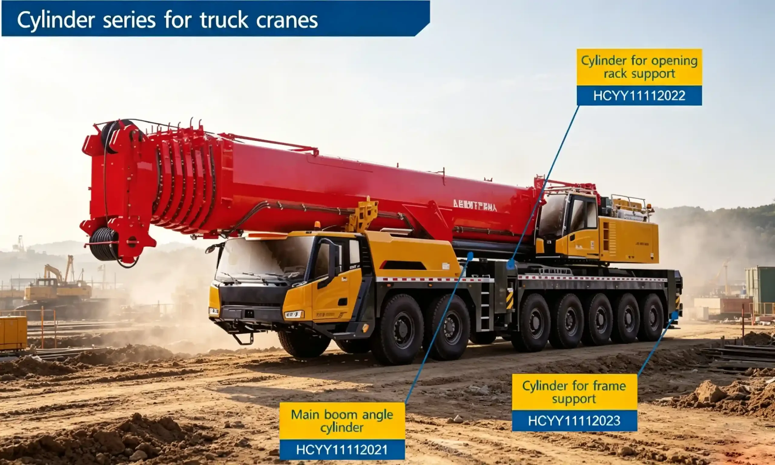
The diagram shows the mounting positions of the main boom lift cylinder (HCYY11112021), outrigger extension cylinder (HCYY11112022), and outrigger jack cylinder (HCYY11112023) within the crane structure.
Full Technical Specifications for the HCYY11112021 Crane Main Boom Lift Hydraulic Cylinder
Every parameter in the table below is derived from crane structural analysis and hydraulic system design requirements. Understanding what each figure means in practice matters more than the numbers themselves — we explain each one below the table.
| Parameter | Value | Engineering Significance |
|---|---|---|
| Model | HCYY11112021 | Unique product identifier for procurement and spare parts |
| Specifications | Φ280 × Φ250 × 3507 mm | Bore × Rod diameter × Stroke. The Φ250 rod is 89% of bore diameter — this ratio is unusually high and indicates the cylinder is designed to resist significant compressive side loads. |
| Working Pressure | 31.5 MPa | Sustained operational pressure. At Φ280 bore, this generates approximately 1,940 kN (197 tonnes) of theoretical push force. |
| Max Withstand Pressure | 39 MPa | Proof test pressure — 1.24× working pressure safety factor. This ensures structural integrity under dynamic shock loads and emergency braking. |
| Stroke | 3,507 mm | Total rod travel. Determines the angular range of boom elevation from minimum to maximum angle. |
| Installation Distance | 4,218 mm | Pin-to-pin distance at full retraction. Critical for crane chassis frame design and boom pivot geometry calculations. |
| Weight | 1,155 kg | Structural mass at this scale is inherent; weight is managed through optimized wall thickness and material selection, not compromised by weight reduction that would affect strength. |
Why a 280mm Bore and 31.5MPa Matters for Crane Main Boom Lift Hydraulic Cylinder Selection
Specifying the wrong bore diameter for a crane boom cylinder is one of the most common engineering errors in crane rebuilds and aftermarket replacements. Undersizing the bore forces the hydraulic system to operate at elevated pressure to generate equivalent force — this accelerates wear on seals, increases heat generation in the hydraulic fluid, and reduces the operational life of both the cylinder and the pump.
A Φ280mm bore at 31.5MPa delivers approximately 1,940 kN of extension force on the push stroke. For the retraction stroke, the effective area is reduced by the rod cross-section (Φ250mm rod area = 49,087 mm²), giving approximately 550 kN of pull force — this asymmetric force profile is typical of boom lift cylinders, where the extension (lifting) force must be significantly higher than retraction.
The maximum withstand pressure of 39MPa means the cylinder barrel, end caps, and rod seal assemblies are tested and validated beyond the rated working pressure. This is particularly important in crane applications where hydraulic pressure spikes occur during dynamic load swinging, sudden braking of the slew rotation, or wind-induced boom oscillation.
Typical Applications for Heavy-Duty Hydraulic Cylinder Crane Main Boom Systems
The HCYY11112021 is suited to crane types and applications where large bore, long-stroke main boom cylinders are standard. Typical deployment scenarios include:
- Truck-mounted cranes (25t–200t): Used in construction sites, utilities, and oil field operations where the boom must be elevated rapidly under full rated load.
- All-terrain cranes: The cylinder must tolerate vibration and shock loads transmitted through the chassis over rough terrain while maintaining boom elevation.
- Rough-terrain cranes: Single-engine machines where hydraulic efficiency matters — a properly sized bore means less engine power consumed to maintain boom position.
- Industrial plant cranes: Used in steel mills, shipyards, and heavy industrial facilities where long service intervals and leak-free operation are non-negotiable.
- OEM crane manufacturing: Procurement for new crane builds where consistent dimensional accuracy across batches is required for production line assembly.
- Crane refurbishment and MRO: Replacement of worn or damaged main boom cylinders where the original OEM part is obsolete or has extended lead times.
Construction Details That Define Long-Term Reliability of a Custom Crane Boom Cylinder
In crane boom cylinders of this bore class, the difference between a cylinder that lasts 10,000 hours and one that fails at 2,000 hours comes down to manufacturing precision and material specification — not just rated pressure.
Cylinder Barrel
Seamless cold-drawn steel tubing, honed internally to Ra 0.2–0.4μm surface finish. This finish range is the critical zone for piston seal service life — too rough accelerates seal wear; too smooth prevents the oil film that seals require.
Piston Rod
Hard chrome plated to 20–25μm thickness on 45# or 40Cr steel substrate. Chrome plating on a Φ250mm rod must be uniform in thickness to avoid differential hardness zones that can crack under bending load.
Seal System
Multi-component seal stack using polyurethane rod seals with PTFE backup rings. Rod wiper seals are inboard of the primary seals to prevent particulate contamination from reaching the pressurized cavity.
End Caps & Ports
Forged steel end caps, threaded or flanged connection depending on application. Hydraulic ports are machined to SAE or BSP standards to match crane OEM hydraulic circuit specifications.
Surface Treatment
External surfaces receive industrial epoxy primer followed by topcoat, matched to customer specification. Trunnion and clevis pin bores are precision-machined after surface treatment to maintain dimensional accuracy.
Pressure Testing
Each cylinder is pressure tested to 39MPa (max withstand pressure) before shipment. Test records are retained for traceability. No external leakage is permitted at test pressure during a minimum 5-minute hold.
Ordering the Right Crane Main Boom Lift Hydraulic Cylinder: What to Confirm Before Procurement
For crane OEMs and MRO procurement teams, getting the dimensional and pressure specifications confirmed before placing an order prevents costly installation failures. The following information is needed to confirm the HCYY11112021 is the correct fit or to specify a custom variant:
- Pin bore diameters: The clevis/trunnion pin bore dimensions at both head and rod end must match the crane boom pivot hardware. Standard and custom bore sizes are available.
- Port type and size: Specify SAE straight-thread, BSPP, or NPT port configuration and size to match the crane’s hydraulic circuit fittings.
- Cushion end requirement: For cranes where the boom reaches end-of-stroke at speed, a hydraulic cushion at retraction end reduces impact loading. Confirm whether internal cushioning is required.
- Seal material: Standard polyurethane seals suit mineral hydraulic oil. If the crane operates with fire-resistant fluid (HFA, HFB, or HFC type), Viton or EPDM seal materials must be specified.
- Quantity and delivery schedule: For OEM production runs, minimum order quantities and batch delivery scheduling can be agreed. Sample orders for engineering validation are accepted.
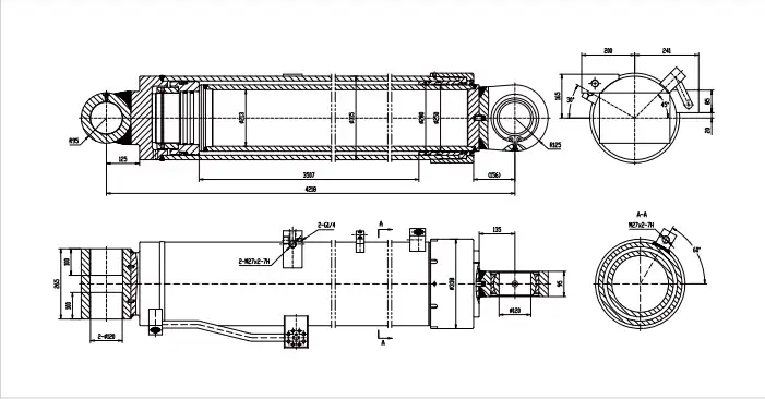
CAD drawings (DXF/PDF format) are available upon request after confirming your application details. Dimensional tolerances are held to ISO 6020/6022 or customer standard, whichever is more stringent.
HCYY11112021 CAD Drawing Reference
Full-dimension CAD drawing available in DXF and PDF format. Contact us with your application details to receive the drawing package.
Frequently Asked Questions About the HCYY11112021 Hydraulic Cylinder for Crane Main Boom Applications
B2B Procurement & OEM Supply
Ready to Specify or Order the HCYY11112021?
Send us your crane model, current cylinder dimensions, and required quantity. We will confirm dimensional compatibility, provide a CAD drawing for your engineering review, and issue a formal quotation — typically within 24–48 business hours.