
The aluminum worm gear reducer is the most widely specified compact right-angle speed reducer for light-to-medium duty applications. Its die-cast aluminum alloy housing delivers a combination of low weight, natural corrosion resistance, and effective heat dissipation that cast iron housings cannot match at the same frame size — without sacrificing the structural rigidity needed to handle the tooth forces in a worm gear pair.
This page covers the full specification range of EPG Canada’s Aluminum Series Worm Gear Reducers: frame sizes, torque and power ratings, standard gear ratios, material specifications, and the mounting configurations available. If you need guidance on which industries and applications benefit most from aluminum housing, see our Aluminum Worm Gearbox Application Guide.
Why Aluminum Housing? The Material Advantage
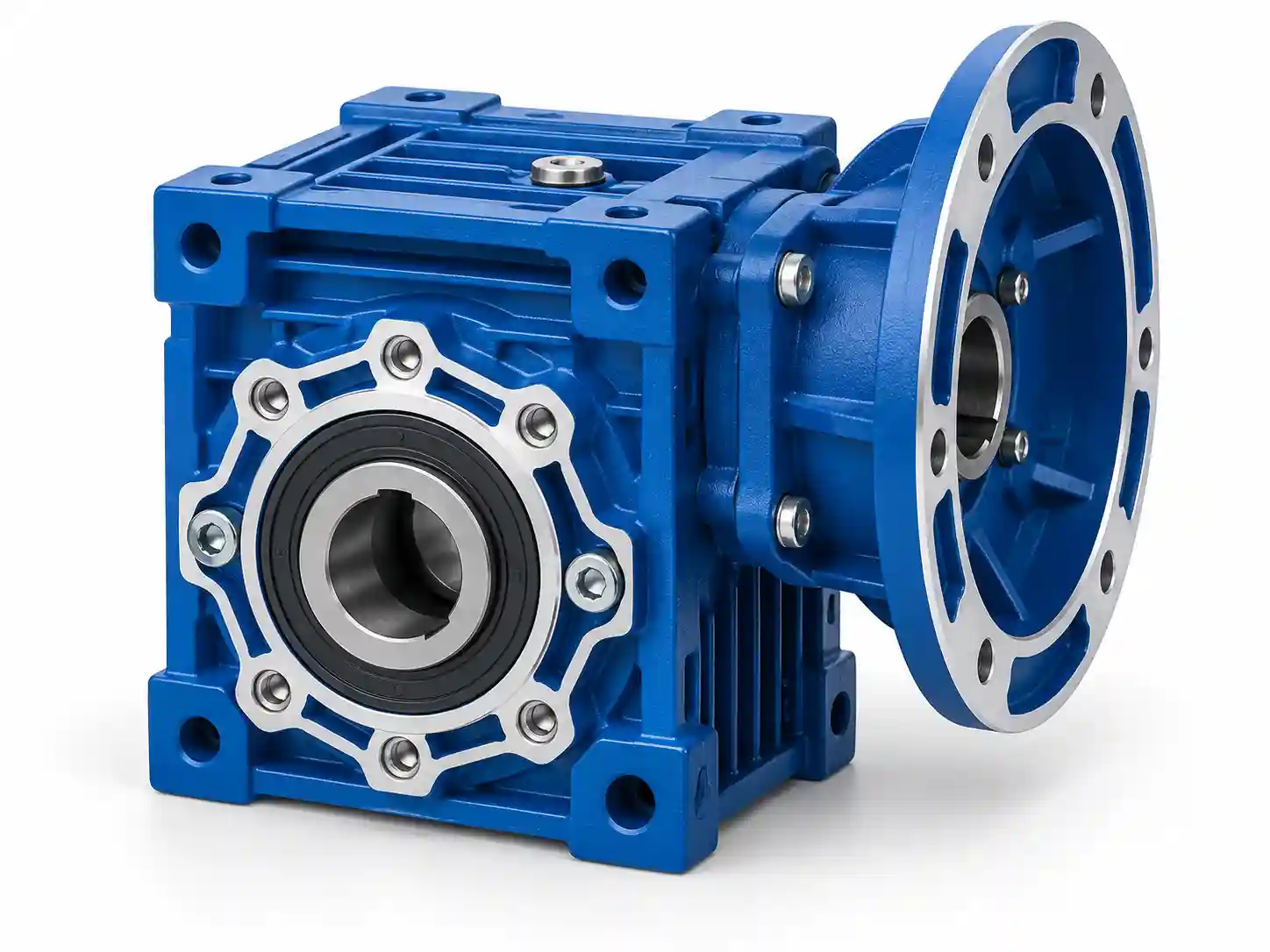
Die-cast aluminum alloy housing — standard on frame sizes 25 through 90
Die-cast aluminum alloy — the ADC12 or similar EN-AC 46000 grade used in these reducers — provides three tangible engineering advantages over cast iron at the same frame size:
30–40% Lower Weight
Aluminum density is roughly 2.7 g/cm³ versus 7.2 g/cm³ for cast iron. A size-63 aluminum reducer weighs approximately 3.5 kg where the equivalent cast iron unit weighs 5–6 kg — significant in elevated, mobile, or operator-handled installations.
Natural Corrosion Resistance
Aluminum forms a stable oxide layer that prevents deeper corrosion — no rust, no paint maintenance. Uncoated cast iron corrodes rapidly in humid or wet environments; aluminum does not, making it the standard choice for food, beverage, pharmaceutical, and outdoor applications.
Better Thermal Conductivity
Aluminum conducts heat roughly 3–4× more efficiently than cast iron. In a worm gearbox — where 10–50% of input power is lost as heat depending on ratio — aluminum housing dissipates that heat faster, reducing oil temperature and extending lubricant and seal service life on intermittent-duty applications.
From size 110 upward, cast iron replaces aluminum in the housing because the larger torques require greater wall section strength. In the specification tables below, sizes 025–090 are aluminum; sizes 110–150 are cast iron.
Frame Sizes and Torque / Power Ratings
The frame size number denotes the center distance (in mm) between the worm shaft axis and the worm wheel shaft axis. Larger center distance = larger gear pair = higher torque capacity. Select the frame size that, at your required ratio, delivers an output torque above your calculated load torque × service factor.
| Frame Size | Center Distance (mm) | Max Output Torque (Nm) | Input Power Range (kW) | Housing Material |
|---|---|---|---|---|
| 025 | 25 | 8 | 0.06 – 0.09 | Aluminum alloy |
| 030 | 30 | 14 | 0.06 – 0.18 | Aluminum alloy |
| 040 | 40 | 26 | 0.09 – 0.37 | Aluminum alloy |
| 050 | 50 | 60 | 0.18 – 0.75 | Aluminum alloy |
| 063 | 63 | 120 | 0.37 – 1.5 | Aluminum alloy |
| 075 | 75 | 220 | 0.55 – 2.2 | Aluminum alloy |
| 090 | 90 | 360 | 0.75 – 4.0 | Aluminum alloy |
| 110 | 110 | 600 | 1.5 – 7.5 | Cast iron |
| 130 | 130 | 980 | 2.2 – 11 | Cast iron |
| 150 | 150 | 1,760 | 4.0 – 15 | Cast iron |
* Max output torque values are at the lowest efficiency point; actual usable torque depends on ratio and service factor. Sizes 110–150 use cast iron housing. Contact our team for exact dimensional drawings for your frame size.
Standard Gear Ratios and Output Speed Reference
All frame sizes in the Aluminum Series cover the same standard ratio range in a single stage. Select the ratio that delivers the required output speed from your motor input speed, then verify the output torque at that ratio.
| Ratio | Output RPM (1,450 input) | Output RPM (960 input) | Typical Efficiency |
|---|---|---|---|
| 5 : 1 | 290 | 192 | ~85–90% |
| 7.5 : 1 | 193 | 128 | ~82–87% |
| 10 : 1 | 145 | 96 | ~80–85% |
| 15 : 1 | 97 | 64 | ~77–82% |
| 20 : 1 | 72 | 48 | ~74–80% |
| 25 : 1 | 58 | 38 | ~72–78% |
| 30 : 1 | 48 | 32 | ~70–76% |
| 40 : 1 | 36 | 24 | ~68–74% |
| 50 : 1 | 29 | 19 | ~66–72% |
| 60 : 1 | 24 | 16 | ~64–70% |
| 80 : 1 | 18 | 12 | ~62–68% |
| 100 : 1 | 14.5 | 9.6 | ~60–66% |
* Efficiency values are approximate and depend on lubricant viscosity, operating temperature, and load. Switching from mineral to synthetic lubricant can recover 5–15% efficiency at ratios above 30:1. For thermal calculations on continuous-duty applications, request the full thermal power rating table.
Worm Shaft and Worm Wheel Material Specifications

Worm Shaft (Input)
- Material: 20Cr alloy steel
- Heat treatment: Carburizing and quenching
- Surface hardness: 56–62 HRC
- Remaining carburized layer after grinding: 0.3–0.5 mm
- Thread profile: Hollow flank worm for maximum wheel contact
- Finish: Precision ground — Ra <0.8 μm
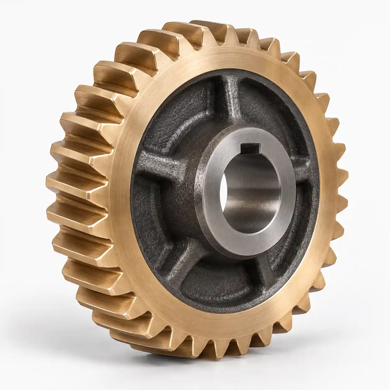
Worm Wheel (Output)
- Standard material: Tin (stannum) bronze alloy — Cu-Sn-10-3
- Option: Aluminum bronze alloy for higher load cycles
- Manufacturing: Centrifugally cast onto a cast iron or steel hub
- Hub material: Cast iron (sizes 025–090) or carbon steel
- Tooth profile: Machined to national standard (GB/T 16444)
Note on bearings: Tapered roller bearings are fitted to the output shaft on all sizes to handle the combined radial and axial (thrust) loads that worm gear geometry generates. The input (worm) shaft runs on deep-groove ball bearings on smaller sizes, with tapered rollers on larger frames. Bearing preload is factory-set and not field-adjustable.
Mounting Configurations
The Aluminum Series supports omnidirectional mounting — the gearbox can be installed in any orientation (horizontal, vertical shaft-up, vertical shaft-down, wall-mounted) without modification to the housing or sealing. Standard output and mounting options cover the majority of industrial design requirements:
Foot Mounted
Standard base-plate mounting. Most common configuration for floor or frame installations.
Flange Mounted
Output or input flange for direct machine mounting. Eliminates the need for a separate bracket.
Hollow Bore Output
Gearbox slides directly over the driven shaft. Saves a coupling and reduces overall assembly length.
Torque Arm
Used with hollow bore mounting to react housing torque against a fixed structure. Standard on conveyor and elevator drives.
Double Output Shaft
Shaft extensions on both sides of the output. Allows a single gearbox to drive two loads simultaneously.
Dual Stage
Two worm stages in series. Extends the ratio range from 100:1 (single) to up to 3,600:1 for very low output speed applications.
Aluminum vs Cast Iron Housing: Which to Specify?
The housing material choice follows from your application conditions, not a general preference. This table summarizes the decision factors:
| Factor | Aluminum Housing | Cast Iron Housing |
|---|---|---|
| Weight | Light ✓ | Heavy |
| Corrosion resistance | High (natural oxide layer) ✓ | Low (requires painting) |
| Heat dissipation | Faster (higher conductivity) ✓ | Slower |
| Torque capacity | Lower (sizes 025–090) | Higher (all sizes) ✓ |
| Vibration damping | Moderate | High ✓ |
| Continuous 24/7 duty | Intermittent–moderate | Preferred ✓ |
| Food / pharma suitability | Preferred ✓ | Not recommended |
| Price | Comparable | Comparable |
How to Size an Aluminum Worm Gear Reducer: 4-Step Process
Calculate the Required Ratio
Ratio = Motor input RPM ÷ Required output RPM. Example: 1,450 RPM motor → 29 RPM output = 50:1 ratio.
Calculate Required Output Torque
Output torque (Nm) = Motor torque (Nm) × Ratio × Efficiency at that ratio. For a 0.75 kW motor at 1,450 RPM (motor torque ≈ 4.9 Nm) with 50:1 at 68% efficiency: 4.9 × 50 × 0.68 = 167 Nm.
Apply Service Factor
Multiply your calculated output torque by the service factor: 1.0 for smooth load, 1.25 for light shock, 1.5–2.0 for heavy shock or cyclic load. Example: 167 Nm × 1.25 (light shock) = 209 Nm required gearbox rating.
Select Frame Size
From the torque table above, select the smallest frame size with a max output torque rating above your service-factored requirement. For 209 Nm at 50:1: size 075 (220 Nm max) is the correct selection. Size 063 (120 Nm) is insufficient. Also verify the thermal rating on continuous-duty applications — contact our technical team for the thermal power data sheet.
Request a Quotation or Technical Data Sheet
Provide your required ratio, output speed, torque, and mounting configuration — we will return the correct model code, dimensional drawing, and pricing within 24 hours.