Beschreibung
What the Hook Lift Tilt Cylinder Actually Does — and Why 290 kg Is Worth It
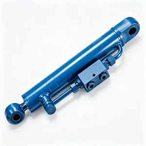
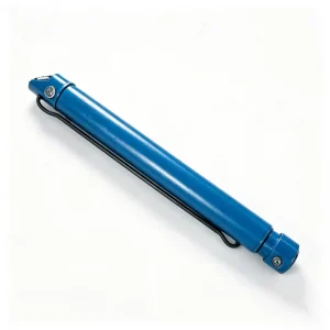
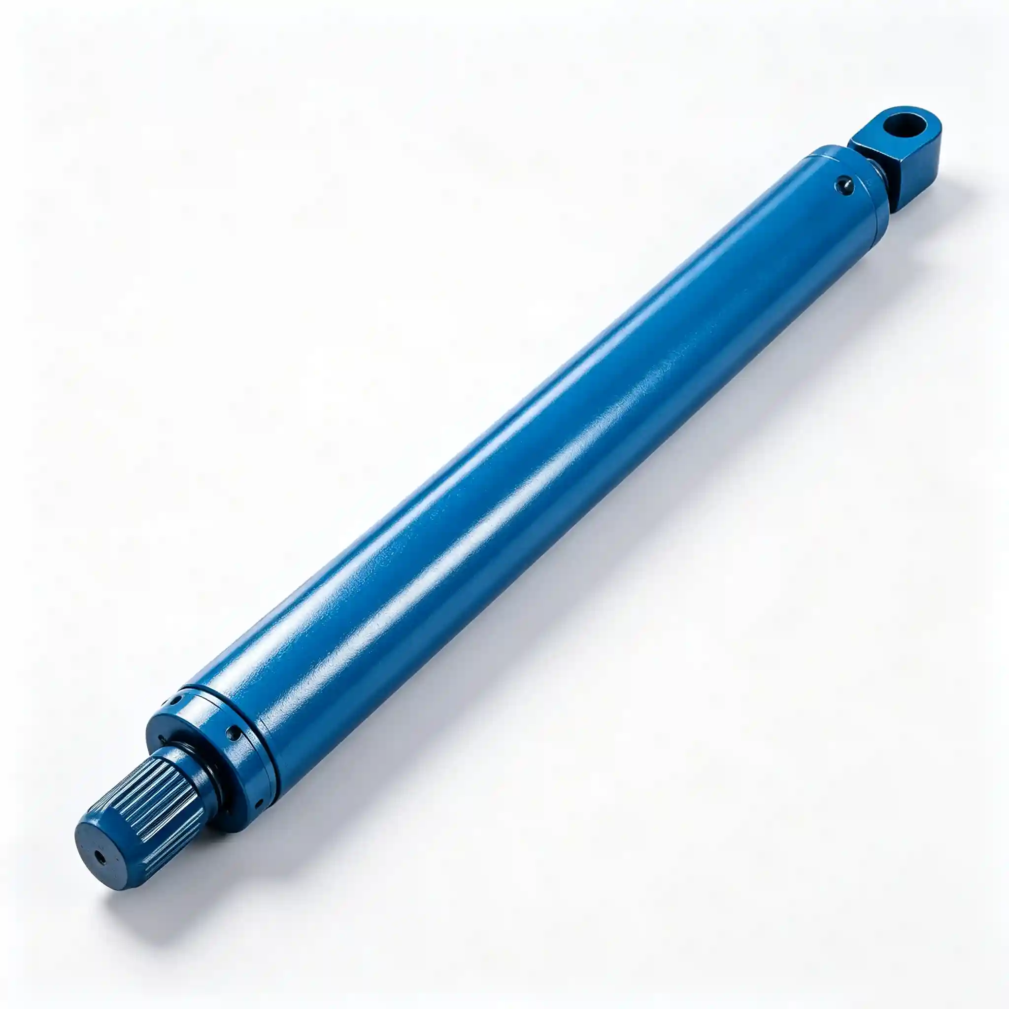
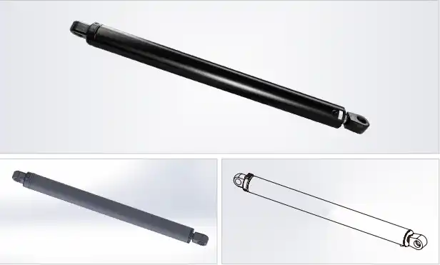
The hook lift tilt cylinder (HCYY11112014) is the workhorse of the entire hooklift system. Every time a skip bin, container, or roll-off body goes up or comes down, this is the cylinder doing the lifting. With a Φ160 mm bore, a 1925 mm stroke, and a working weight of 290 kg, it is — by every measurable dimension — the most demanding component in the hydraulic circuit.
In a typical hooklift sequence, the tilt cylinder extends to raise the hooklift arm from the horizontal road position to the full tilt angle needed to slide the container onto the subframe. The stroke of 1925 mm translates directly into the arm travel arc — longer stroke means a wider sweep, which in turn determines the maximum container length and off-ground height the truck can handle. At 30 MPa working pressure, the Φ160 bore develops a theoretical push force of approximately 603 kN — over 60 tonnes of linear force, acting through the arm pivot to generate the torque needed to lift fully loaded skips.
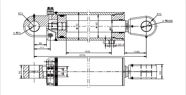
The installation distance of 2376 mm (center-to-center, retracted) defines the physical footprint of this cylinder on the subframe. This is a non-negotiable dimension when specifying a replacement — even a 10 mm deviation changes the arm geometry and alters the effective mechanical advantage at the pivot point.
Technical Specifications — HCYY11112014 Hooklift Tilt Hydraulic Cylinder
| Parameter | Value | Engineering Context |
|---|---|---|
| Model | HCYY11112014 | Hooklift tilt cylinder series |
| Bore × Rod × Stroke | Φ160 × Φ80 × 1925 mm | Large-bore, long-stroke configuration for maximum arm torque |
| Working Pressure | 30 MPa | Push force ≈ 603 kN at rated pressure |
| Max Withstand Pressure | 35 MPa | 17% overpressure margin; burst tested before shipment |
| Stroke (Trip) | 1925 mm | Full arm travel from horizontal to maximum tilt position |
| Installation Distance | 2376 mm | Pin-to-pin span (retracted); critical for arm geometry |
| Weight | 290 kg | Accounts for ~60–70% of total hooklift cylinder system mass |
Why Bore Size and Stroke Length Drive Every Hooklift Design Decision
In any hydraulic actuator, force output is purely a function of bore area and pressure: F = P × A. At 30 MPa and a Φ160 bore (area = 20,106 mm²), you get approximately 603 kN of push force. That force — transmitted through the tilt arm linkage — becomes the torque at the pivot point that lifts the load. If the hydraulic system can’t deliver that force consistently, even a fully-rated 30-tonne container will stall the arm mid-cycle.
The 1925 mm stroke isn’t arbitrary either. Hooklift arm geometry is a fixed trigonometric relationship: the angle the arm sweeps through from road position to full tilt is determined by the cylinder stroke and the pivot distance. Replacing this cylinder with a shorter-stroke unit doesn’t just change the arm angle — it changes the effective hook height above the ground, potentially making the truck unable to engage standard-height containers.
The Φ80 mm rod diameter is also deliberately oversized relative to the bore. At a 2:1 bore-to-rod ratio, the annular pull force (retraction) is approximately 452 kN — enough to drag a loaded container back onto the subframe even on uneven ground or a slight uphill gradient. Undersized rod diameters are a leading cause of column buckling failures on long-stroke cylinders under eccentric load conditions.
The 35 MPa withstand pressure — a 17% margin over rated working pressure — absorbs transient spikes from fast valve actuation, cold-start viscosity surges, and relief valve response lag. For a 290 kg cylinder operating at full stroke, the consequences of a seal blow-out mid-cycle aren’t just a maintenance cost: they’re a safety event.
Skip Loader and Roll-Off Truck Applications — Where This Tilt Cylinder Earns Its Keep
The HCYY11112014 is specified for the tilt cylinder position on hooklift (skip loader) trucks operating across the following industries and duty cycles:
- High-volume waste management fleets — 8–12 load cycles per shift, where consistent extension speed and smooth deceleration at end-of-stroke prevent container shock-loading
- Construction waste skip hire — mixed-density loads (concrete, timber, metal) that generate asymmetric container center-of-gravity, putting high bending loads through the rod at partial extension
- Industrial liquid container transport — where slow, controlled arm movement during tilt is critical for avoiding slosh-induced overturning moments
- Recycling and materials recovery facilities — multi-stream containers handled in fast-turnaround environments where cycle time directly impacts throughput revenue
- OEM hooklift system assembly — truck body builders requiring a dimensionally consistent, pressure-tested tilt cylinder across multiple production batches
Construction and Material Specification
Cylinder Tube
Cold-drawn seamless steel (ST52 / E355), precision-honed ID to Ra ≤ 0.4 μm. Wall thickness calculated for 35 MPa burst with a minimum safety factor of 2.5.
Piston Rod
Φ80 mm, 45# steel with induction-hardened outer surface and hard chrome plating ≥ 25 μm. Slenderness ratio engineered to prevent Euler column buckling under full-stroke eccentric loading.
Seal System
Polyurethane (PU) piston and rod seals, with a scraper wiper and secondary dust lip. Rated −25 °C to +85 °C for year-round operation across northern European and North American climates.
End Mounts
Heavy-duty clevis or trunnion pin ends (specify configuration), machined from forged steel for fatigue resistance under high-cycle alternating loads. Pin bore tolerances held to H7.
Surface Protection
Exterior barrel: two-coat epoxy primer + polyurethane topcoat, minimum 80 μm DFT. Rated for salt-spray exposure (ISO 9227) common in coastal and winter road-salt environments.
Quality Testing
Each cylinder is hydrostatically tested to 35 MPa before shipment. Leakage check at working pressure with 5-minute hold. Stroke function test at no-load to confirm smooth travel and end-cushion performance.
Installation and Replacement Notes for the Hooklift Tilt Cylinder
At 290 kg, this cylinder requires appropriate lifting equipment for safe handling during installation — a chain hoist or boom crane rated for at least 500 kg is recommended to allow controlled positioning without personnel strain. Critical installation checkpoints:
- Confirm the 2376 mm installation distance before ordering. Measure pin-to-pin on the existing cylinder, not the subframe brackets — bracket wear can introduce 5–15 mm of false clearance.
- Inspect pivot pin bores for out-of-round wear before installing a new cylinder. A worn bore creates point contact on the pin, concentrating stress and reducing fatigue life of both the pin and the cylinder eye.
- Bleed thoroughly — on a 1925 mm stroke cylinder, entrapped air can cause significant end-of-stroke hammering that is frequently misdiagnosed as a structural issue.
- Check flow control valve settings after installation. The extension speed of the tilt cylinder controls container impact at the point of arm contact — too fast causes structural shock to both the arm and the container; too slow costs cycle time.
- Apply anti-seize compound to all pivot pins before assembly. Galvanic corrosion between steel pins and painted steel or aluminum brackets is a common cause of seized pivots that damage the cylinder eyes during removal.
Hydraulic Cylinder Mounting Position — Hooklift Truck System
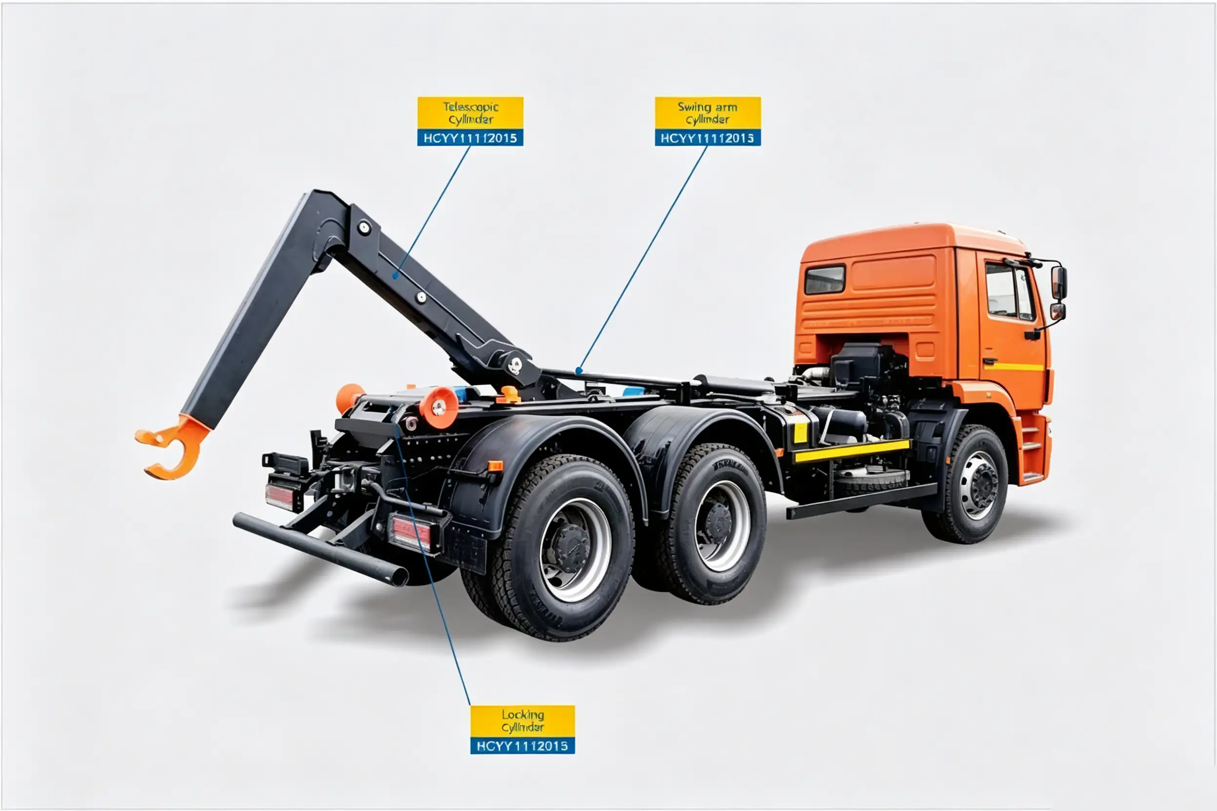
The tilt cylinder is the primary actuator — driving the full arm rotation from road position to maximum tilt angle on every load and unload cycle.
Common Questions — Hooklift Tilt Hydraulic Cylinder
Can I use a shorter-stroke cylinder if the original is unavailable?
Not without significant consequences. Stroke length directly determines the arm sweep angle. A shorter stroke reduces the maximum tilt angle, which in turn lowers the hook height above the ground. If the hook can’t reach the container’s lift bracket, loading fails entirely. You’d also need to re-engineer the end-stop geometry of the arm to avoid over-travel in the opposite direction. In short — if the original stroke spec isn’t available, the right move is to order to the OEM dimension and wait, not to improvise with what’s on the shelf.
What causes a tilt cylinder to drift down under load?
Cylinder drift under load is almost always a piston seal failure rather than an external leak. The piston seal allows hydraulic fluid to bypass from the high-pressure (cap) side to the rod side, causing the cylinder to retract slowly even with the control valve in neutral. This is confirmed by isolating the cylinder ports — if it drifts with the lines capped, the seal is the culprit. If it only drifts with lines open, look at the control valve or load-holding check valve. In either case, continued operation risks a sudden, uncontrolled arm drop — which is a serious safety hazard on a loaded truck.
How do I know if the rod is bent without removing the cylinder?
Three field indicators: (1) Uneven rod wiper seal wear — if the wiper is consistently wearing on one side, the rod is entering the gland off-center due to deflection. (2) Oil weeping from the rod seal at partial extension but not at full extension — deflection is maximum at mid-stroke and reduces as the rod shortens. (3) Visible lateral movement of the rod tip during slow extension — hold a straightedge against the cylinder barrel and watch the rod run out. Any deviation over 1.5 mm across a 1-meter run warrants replacement before the rod contacts the barrel bore and causes scoring damage.
What’s a realistic service life for this tilt cylinder?
With proper hydraulic fluid maintenance (oil change at OEM intervals, filter at 500 hours), aligned pivot pins, and no rod impact damage, seal kits typically need replacement at 3–5 years in municipal fleet service (≈ 10,000–15,000 load cycles). The barrel and rod have an expected life of 10–15+ years if sealing is maintained and the rod is protected from impact. The two fastest ways to shorten service life are running degraded hydraulic fluid (moisture and oxidation attack PU seals) and ignoring minor rod seal weeps until the rod surface is pitted.
Is the HCYY11112014 available as a seal-repair kit separately?
Yes. We supply a matched seal kit (piston seal, rod seal, wiper/scraper, and O-ring set) for the HCYY11112014 as a separate line item. This is the cost-effective option when the barrel and rod are in good condition. Note that re-sealing a long-stroke cylinder requires either in-shop disassembly with appropriate fixtures to prevent rod handling damage, or dispatch to a hydraulic service shop with a vertical test bench. Contact us for kit pricing and a parts diagram.
Sourcing the HCYY11112014 for Your Fleet or Production Line?
We supply the hooklift tilt cylinder to fleet operators, truck body builders, and hydraulic distributors across North America, Europe, and Australia. Bulk orders, full hydrostatic test certificates, dimensional drawings, and seal kit packages are all available. Lead times and freight options on request.
Model: HCYY11112014 · Φ160×Φ80×1925 · 30 MPa / 35 MPa · 1925 mm stroke · 2376 mm installation distance · 290 kg