
How Much Torque Does a Right Angle Planetary Gearbox Need?
Torque is the number engineers reach for first when sizing a gearbox—and for good reason. Get the torque rating wrong and the unit either fails prematurely or sits at a fraction of its capacity, both of which cost money. But “how much torque does my gearbox need” is actually three separate questions bundled into one: how much continuous torque, how much peak torque, and what rated torque does the gearbox need to survive both over its intended service life.
This article walks through each of those questions with the calculations and decision logic behind them. The goal is to give you the torque specification you can take to a gearbox selection table—not a rough guess, but a defensible number based on your actual application.
Understanding the Three Torque Values That Matter
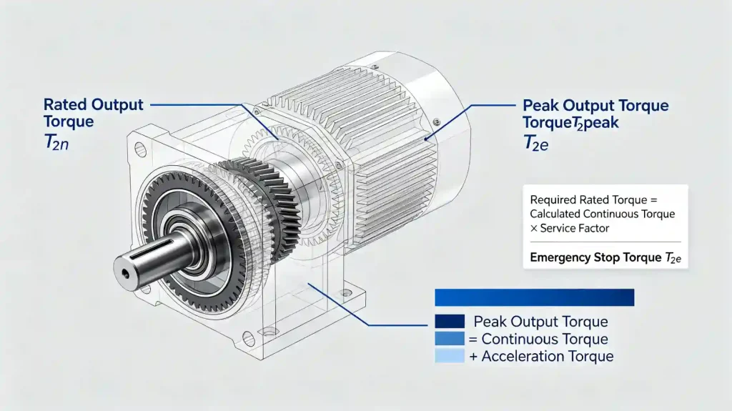
A right angle planetary gearbox datasheet lists several torque values. The three you need to understand before selecting a unit are:
Rated output torque (T₂n) — the torque the gearbox can sustain continuously under normal operating conditions without exceeding its thermal or mechanical limits. This is the primary selection parameter for steady-state applications.
Peak output torque (T₂peak) — the maximum torque the gearbox can handle for short durations—typically during motor acceleration, deceleration, emergency stops, or load spikes. Peak torque ratings are typically 2–3 times the rated torque, depending on the gearbox design. The gearbox can handle this torque intermittently; it cannot sustain it continuously.
Emergency stop torque (T₂e) — some manufacturers specify a maximum allowable torque for emergency stop events only, which may be higher than the peak torque rating. This covers the brief, high-magnitude torque spike that occurs when a servo drive trips into an emergency stop. Not all datasheets include this value separately—check the manufacturer’s documentation.
Your application generates at least two of these: a continuous torque during normal operation, and a peak torque during acceleration or abnormal events. Both must be within the gearbox’s ratings. A gearbox with adequate continuous torque but insufficient peak torque rating will eventually suffer fatigue damage at the gear teeth or output bearings, even if the average loading looks fine.
Calculating Required Continuous Output Torque
The continuous torque at the gearbox output is the torque required to maintain the load in motion under normal operating conditions. It comes from the load itself—friction, process forces, gravity components, and the torque required to move the load at the required speed.
For a simple rotary load driven directly by the gearbox output shaft:
Continuous Output Torque = Load Torque + Friction Torque
For a linear load converted to rotary motion (rack and pinion, ball screw, belt and pulley):
Continuous Output Torque = (Force × Pitch Radius) ÷ Mechanical Efficiency of Drive Element
Where force is the total force required to move the load (gravity + friction + process force) and pitch radius is the radius of the driving sprocket, pinion, or pulley.
Be thorough about what’s included in that force calculation. Missing a friction component or underestimating process forces is one of the most common reasons gearboxes run hotter than expected or have shorter than expected service life. In doubt, add a margin rather than relying on a theoretical minimum.
Calculating Required Peak Torque
Peak torque occurs during acceleration. The total peak torque at the gearbox output has two components: the torque to overcome load friction and process forces (same as continuous torque), plus the additional torque needed to accelerate the load’s inertia.
Peak Output Torque = Continuous Torque + (Load Inertia × Angular Acceleration)
Angular acceleration in rad/s² is calculated from the required speed change and the time allowed for it:
Angular Acceleration = ΔSpeed (rad/s) ÷ Acceleration Time (s)
For a servo application with a fast motion profile—say, 0 to 60 RPM in 0.1 seconds:
ΔSpeed = 60 RPM × (2π ÷ 60) = 6.28 rad/s
Angular Acceleration = 6.28 ÷ 0.1 = 62.8 rad/s²
If load inertia at the output is 0.05 kg·m²:
Acceleration Torque = 0.05 × 62.8 = 3.14 Nm
Add this to the continuous torque to get peak torque. Then apply a service factor and compare to the gearbox peak torque rating.
Note: in servo systems, the servo drive and motor are also participating in this acceleration. The peak torque at the gearbox output equals the motor peak torque multiplied by the gear ratio multiplied by transmission efficiency. Verify this doesn’t exceed the gearbox peak torque rating. Servo drives can produce very high peak currents for brief periods—the mechanical components downstream need to be rated for those peak torques.
Applying the Service Factor
Calculated torque values represent theoretical minimums under ideal conditions. Real applications involve load variations, minor misalignment, vibration, temperature effects, and occasional overloads. The service factor accounts for this gap between theory and reality.
Required Rated Torque = Calculated Continuous Torque × Service Factor
The gearbox rated torque must exceed this value. Common service factor ranges:
| Application Type | Typical Service Factor |
|---|---|
| Smooth, uniform load, continuous duty | 1.0 – 1.25 |
| Light shock, moderate variation, 8–16 hr/day | 1.25 – 1.5 |
| Moderate shock, variable load, continuous duty | 1.5 – 2.0 |
| Heavy shock, reversing loads, high cycle rate | 2.0 – 2.5 |
| Extreme shock, impact loads, very high cycle rate | 2.5 and above |
These are general guidelines. Your gearbox manufacturer’s application factor tables, or relevant industry standards such as AGMA, provide more specific guidance for your application type. When the application is unusual or the duty cycle is not clearly defined, err toward a higher service factor. The cost of a slightly larger gearbox is far less than an early field failure.
Rated Torque vs. Peak Torque: Both Must Be Checked Independently
A common mistake: verifying the gearbox rated torque is sufficient but not checking the peak torque rating separately. These are independent checks with different consequences if failed.
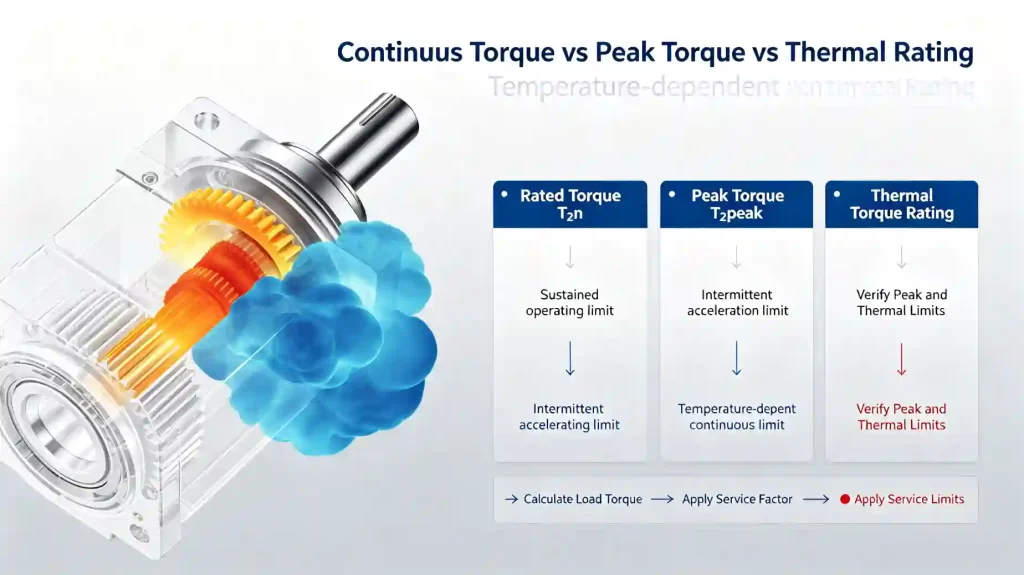
Exceeding the rated torque continuously causes thermal overload—the gearbox runs hotter than designed, lubricant degrades faster, and bearing and gear life are significantly shortened. The failure may not be immediate, but service life will be a fraction of what it should be.
Exceeding the peak torque rating in short bursts causes mechanical fatigue—micro-cracks in gear tooth roots, Hertzian contact fatigue on bearing raceways. Again, failure may not be immediate, but each overload event accumulates damage. Eventually a tooth breaks or a bearing fails, often at a moment that seems unrelated to any particular overload event.
Both must be checked. A gearbox with a rated torque of 50 Nm and a peak torque of 120 Nm must see no more than 50 Nm continuously and no more than 120 Nm during transients. If your application’s acceleration profile generates 130 Nm peak at the output, the gearbox is undersized for peak torque even if continuous loading is well within spec.
The Thermal Torque Rating: What It Is and When It Applies
Some right angle planetary gearbox datasheets include a thermal torque rating in addition to the mechanical rated torque. The thermal rating is the torque at which the gearbox reaches its maximum allowable operating temperature under continuous duty in a standard ambient environment—typically 20–25°C.
If the thermal rated torque is lower than the mechanical rated torque for your operating conditions, the thermal limit governs the selection. This situation arises when:
- The gearbox operates in a high ambient temperature environment.
- The duty cycle is 100%—no rest periods for the gearbox to cool.
- Ventilation around the gearbox is restricted.
- The installation orientation reduces cooling compared to the standard test condition.
For most servo applications with duty cycles below 100% and standard ambient temperatures, the mechanical rated torque is the governing limit. For continuous-duty applications in hot environments, check the thermal rating explicitly.
A Worked Torque Sizing Example
Application: right angle planetary gearbox driving a conveyor roller through a sprocket, with occasional jam loads.
- Normal conveyor load torque at output: 18 Nm
- Friction torque in drive system: 4 Nm
- Load inertia at output: 0.02 kg·m²
- Acceleration from 0 to operating speed in 0.5 seconds
- Operating speed: 120 RPM output
- Application type: moderate shock, 16 hr/day operation
Continuous torque: 18 + 4 = 22 Nm
Angular acceleration: 120 RPM = 12.57 rad/s → 12.57 ÷ 0.5 = 25.1 rad/s²
Acceleration torque: 0.02 × 25.1 = 0.5 Nm
Peak torque: 22 + 0.5 = 22.5 Nm (acceleration adds little here due to low inertia and slow ramp)
Service factor: Moderate shock, 16 hr/day → 1.5
Required rated torque: 22 × 1.5 = 33 Nm
Required peak torque: 22.5 Nm (no service factor typically applied to peak torque separately—the peak rating itself already has a margin built in, but confirm with the manufacturer)
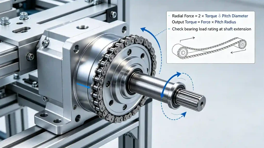
Result: select a gearbox with rated output torque ≥ 33 Nm and peak torque ≥ 22.5 Nm. Also verify the radial load from the sprocket drive is within the output shaft bearing rating.
How Gearbox Frame Size Relates to Torque Rating
Within a right angle planetary gearbox product family, larger frame sizes deliver higher torque ratings. Frame size is usually defined by the output flange diameter or housing width, and each frame size has a range of available ratios at its associated torque rating.
A few things worth knowing:
- Torque rating can vary within the same frame size depending on ratio. A two-stage unit at a high ratio (e.g. 100:1) may have a lower rated torque than the same frame at a lower ratio (e.g. 10:1), because the additional gear stage has its own mechanical limits. Always check the rated torque at the specific ratio you’re selecting, not just the maximum frame torque.
- Radial load capacity also scales with frame size. A larger frame has larger output bearings and higher radial load ratings—relevant if your application applies significant side loads to the output shaft.
- Moment load capacity—resistance to bending forces on the output flange—also scales with frame size. Relevant for cantilevered output arrangements.
Signs You’ve Undersized the Torque Rating
If a gearbox is undersized on torque, the symptoms appear over time rather than immediately. Watch for:
- Elevated operating temperature — the gearbox housing runs noticeably hotter than ambient under normal load. This indicates the gearbox is working harder than its thermal design allows.
- Premature oil seal failure — high temperatures degrade seal lip materials. If seals fail before expected service intervals, overloading is a common cause.
- Increasing backlash over time — gear tooth wear accelerates under overload conditions, causing backlash to grow faster than normal.
- Unusual noise or vibration — gear mesh noise often increases as teeth wear unevenly from overload conditions.
- Short bearing life — bearings failing significantly before the expected L10 life is a strong indicator that loads exceed what the gearbox was sized for.
If any of these symptoms appear, review the actual torque loading against the gearbox rating—particularly the peak torques during acceleration and any jam or impact events the machine has experienced.
Frequently Asked Questions
What is the difference between rated torque and peak torque in a gearbox?
Rated torque is the torque the gearbox can sustain continuously without exceeding its mechanical or thermal limits. Peak torque is the maximum torque it can handle for short durations—typically a few seconds during acceleration or braking events. Both must be checked against your application’s actual torque profile. Failing the continuous rating causes thermal damage; failing the peak rating causes mechanical fatigue.
Do I need to apply a service factor to peak torque as well as continuous torque?
Typically, the service factor is applied to the continuous torque calculation to determine the required rated torque. Peak torque is compared directly to the gearbox peak torque rating, which already includes a factor of safety against mechanical failure. However, if your application involves frequent or unpredictable peak events—repeated jam loads, heavy shock, high-cycle emergency stops—it’s worth discussing the specific duty with the manufacturer before finalizing the selection.
How do I calculate the torque required to move a linear load?
Convert the linear force to a rotary torque using the radius of the driving element: Torque = Force × Radius. For a ball screw: Torque = (Force × Lead) ÷ (2π × Screw Efficiency). For a rack and pinion: Torque = Force × Pinion Pitch Radius. For a belt and pulley: Torque = Force × Pulley Radius. These give the output torque required at the gearbox. Divide by the gear ratio to find the required motor torque, accounting for gearbox efficiency.
Is it safe to run a gearbox at 100% of its rated torque continuously?
Technically the rated torque is the continuous limit, so running at 100% is within spec. In practice, for applications with long expected service life, targeting 70–80% of rated torque under normal operating conditions leaves margin for load variations, temperature effects, and wear over time. Running consistently at 95–100% of rated torque leaves very little safety margin for real-world variability.
Does the torque rating change with gear ratio in the same frame size?
Yes, in some product lines. The rated output torque at the gearbox output can vary depending on which stage—the bevel input or a planetary stage—is the limiting factor at a given ratio. Two-stage units at high ratios may have lower output torque ratings than single-stage units in the same housing. Always verify the rated torque at the specific ratio you are selecting, not just the maximum frame-size torque.
What happens to gearbox torque rating at elevated temperatures?
At ambient temperatures above the standard test condition (typically 20–25°C), the thermal torque rating decreases. The gearbox generates heat from its own gear mesh losses; at higher ambient temperatures, it has less cooling capacity to dissipate that heat. For installations in hot environments, check the manufacturer’s thermal derating curve for the specific unit and derate the rated torque accordingly.
Getting the Torque Specification Right Before You Order
Torque sizing is the most consequential part of gearbox selection. Too small, and the unit fails early. Too large, and you’ve paid for capacity you don’t need—and in servo systems, you may have made inertia matching harder. The right torque rating is the one that covers your continuous and peak requirements with an appropriate service factor, leaving reasonable operating margin without excessive oversizing.
If you’re working through a torque calculation and want to verify the numbers before specifying a right angle planetary gearbox, send the application data. A quick check against the actual product ratings is often faster than working through a general catalog selection on your own.
EPG Canada Sales Representative Co., Ltd provides gearbox selection support and technical coordination for Canadian OEMs and industrial equipment manufacturers across North America.
Email: [email protected]
Phone: +1-604 719 2870
Address: 10891 Hogarth Dr, Richmond, BC V7E 3Z9, Canada
For torque sizing support, include:
- Load description and calculated continuous torque at the output (Nm)
- Load inertia (kg·m²) and acceleration profile
- Peak torque events and their frequency
- Application type and daily operating hours
- Ambient temperature and installation environment
- Motor make, model, rated torque, and peak torque
- Required gear ratio and output speed
See the full planetary gearbox range, explore the right angle planetary gearbox series, or contact us here to discuss your torque requirements.