Açıklama
HCYY11112011 — Articulating Boom Lift Hydraulic Cylinder | Φ100×Φ80×1458, 21 MPa
The HCYY11112011 is the folding boom angle cylinder — the actuator that drives the upper (knuckle) section of an articulating boom lift through its full angular range. At 1458 mm stroke, 137 kg, and a 1899 mm installation distance, it is simultaneously the longest-stroke and heaviest cylinder in this product line. It is also the most mechanically complex: unlike a simple lifting cylinder that pushes in one direction and holds, the folding boom angle cylinder must generate large force in both extension and retraction directions, across an angular range that can exceed 135° and includes a load-direction reversal mid-travel.
The Φ80 mm rod on a Φ100 mm bore — a rod-to-bore ratio of 0.80 — is the most immediate indicator of this cylinder’s unique demands. That ratio is close to the theoretical maximum for a conventional double-acting cylinder, and it was chosen for a specific reason: on an articulating boom, the cylinder must actively push the upper boom both upward and downward with comparable force levels. The thick rod keeps the retraction-side area close to the extension-side area, so the cylinder does not become dramatically weaker in one direction — a property that matters when the machine needs to control the upper boom’s descent speed against wind load, or pull the boom past vertical into a negative working angle.
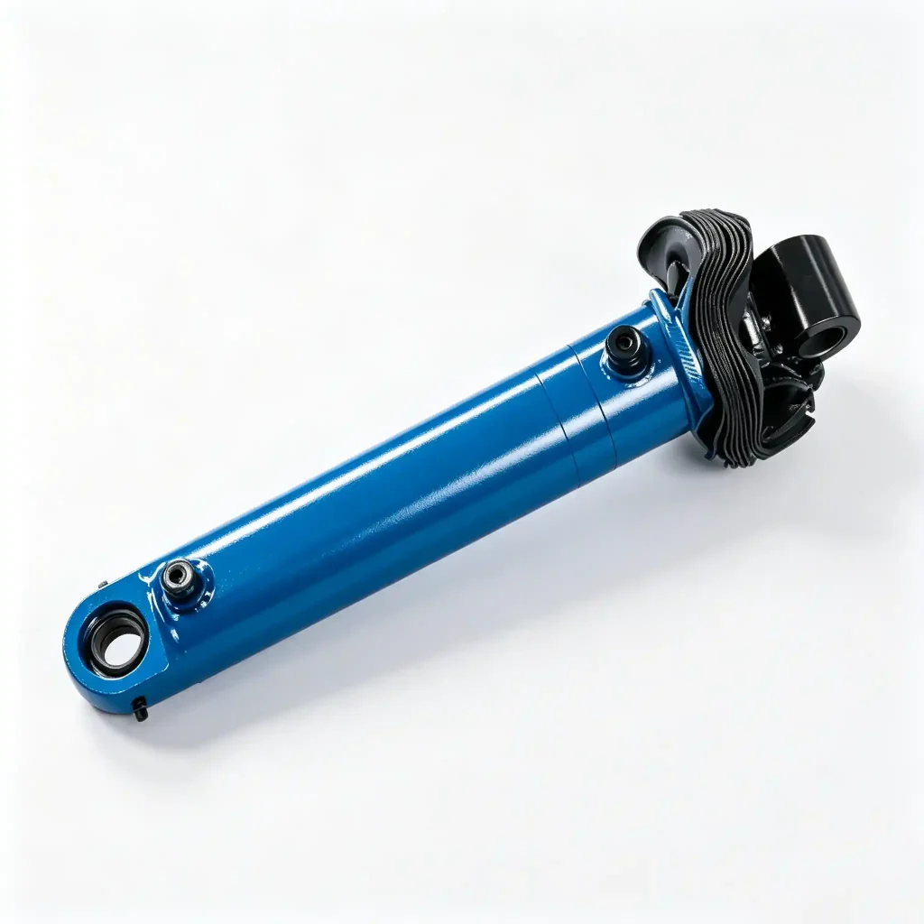
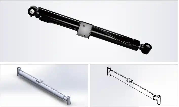
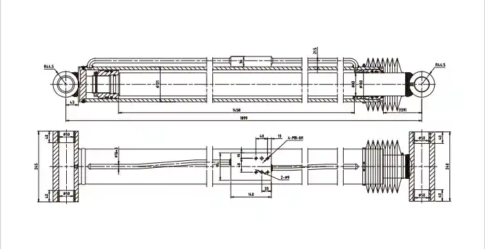
Technical Specifications — Folding Boom Angle Cylinder, Φ100 Bore, 21 MPa, 1458 mm Stroke
| Parameter | Value | What It Means in Practice |
|---|---|---|
| Model | HCY11112011 | OEM part reference |
| Bore × Rod × Stroke | Φ100 × Φ80 × 1458 mm | Rod-to-bore ratio 0.80 — near-symmetric force in both directions; extension force ≈ 164.9 kN, retraction force ≈ 65.9 kN at 21 MPa |
| Working Pressure | 21 MPa | Shared with the main boom circuit on most platforms using this cylinder class |
| Max Withstand Pressure | 32 MPa | 1.52× working pressure — higher absolute margin (11 MPa) than the standard 1.5× ratio implies |
| Stroke | 1458 mm | Longest in this range — seal travels 1458 mm of chrome rod surface per cycle |
| Installation Distance | 1899 mm | Retracted pin-to-pin length; must fit within the stowed boom envelope for transport height compliance |
| Weight | 137 kg | Heaviest in this range — rated lifting equipment and at least two trained technicians required for safe handling |
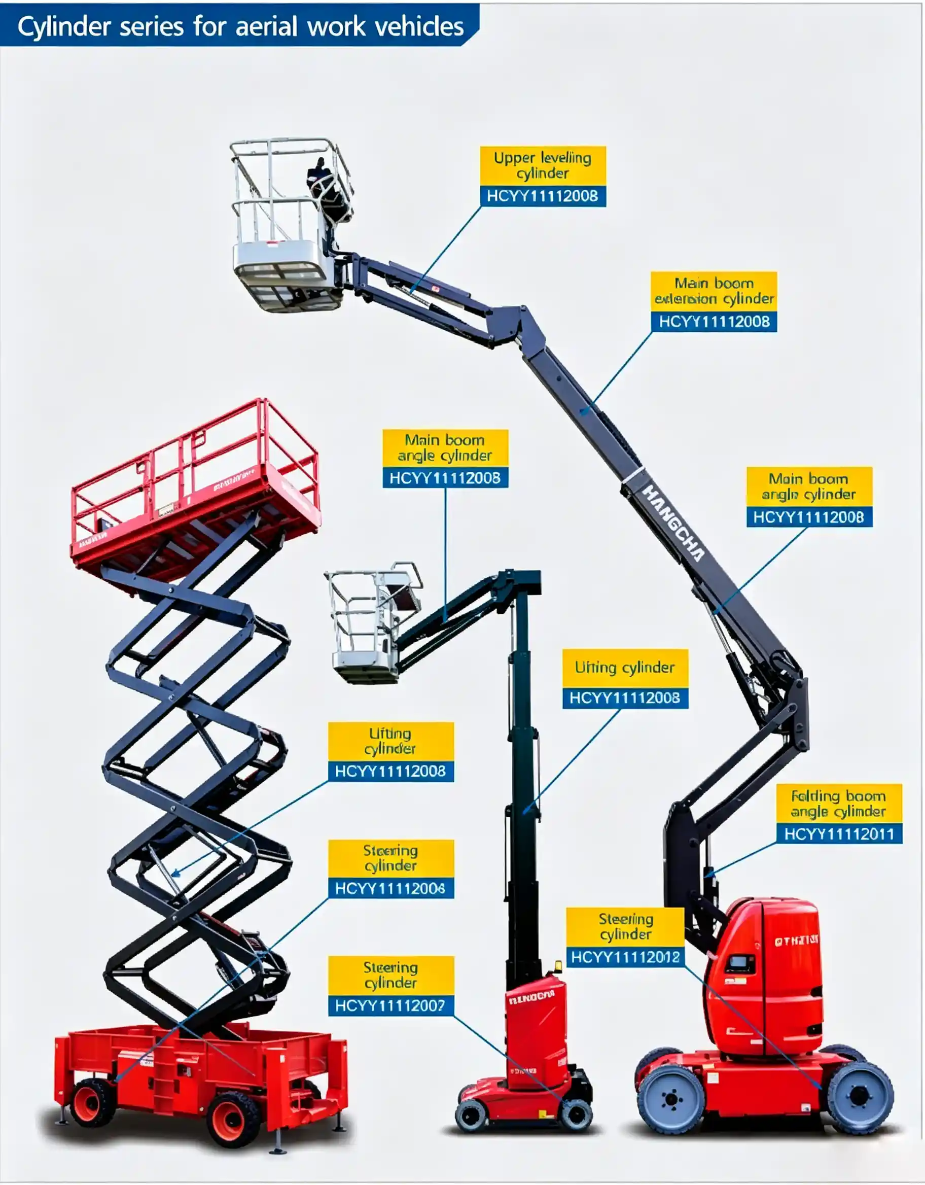
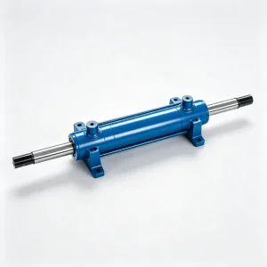
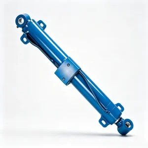
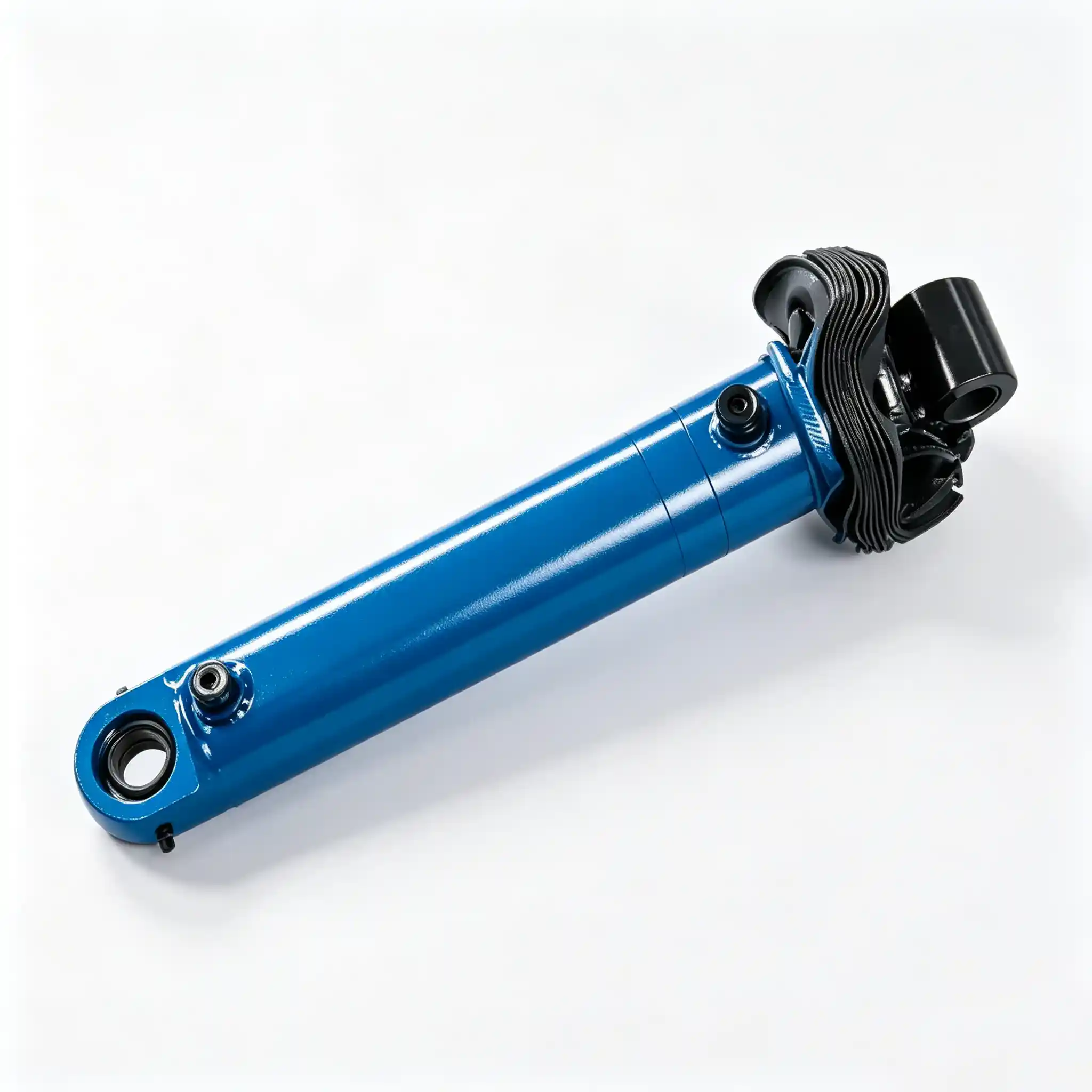
Installation position reference — HCYY11112011 folding boom angle cylinder in articulating boom lift hydraulic layout
Load Direction Reversal: What Happens to This Cylinder as the Folding Boom Crosses Horizontal
On a telescopic boom lift, the main angle cylinder is always in compression when the boom is elevated — gravity pulls the boom down, and the cylinder pushes back up. The load direction never changes sign. On an articulating boom, the folding section can travel from well below horizontal (stowed transport position) through horizontal to a high working angle above horizontal, and then — on machines with negative-angle capability — past vertical and back down to a position where the platform is lower than the knuckle pivot.
As the upper boom crosses the horizontal position during this travel, the gravitational moment acting on the cylinder reverses direction. Below horizontal, the cylinder must push against gravity to raise the boom. Above horizontal, gravity assists the extension and the cylinder must control the rate of rise — and then hold the position. When the boom goes past vertical, the cylinder must actively retract to bring the boom back down, fighting gravity in the retraction direction.
This reversal is why the Φ80 mm rod is essential. The retraction force at 21 MPa is determined by the annulus area — bore area minus rod area. With Φ100 bore and Φ80 rod: annulus area = (100² − 80²) × π/4 = (10000 − 6400) × 0.785 = 2,827 mm². Retraction force = 2,827 mm² × 21 MPa ≈ 59.4 kN. That is the force available to pull the upper boom back from a negative working angle, or to control its descent against an upward wind load. On a machine designed to work at negative angles, 59.4 kN retraction force is not an engineering luxury — it is the minimum required by the load analysis.
1458 mm Per Cycle: Seal Life in a Long-Stroke, High-Frequency Articulating Boom Cylinder
Every time the folding boom completes one full raise-lower cycle, the rod seal and wiper travel 2916 mm of chrome rod surface — 1458 mm of rod on extension, 1458 mm on retraction. On a construction site machine repositioned 15–20 times per shift, that accumulates to 40–60 meters of seal travel per day. Over a 1000-hour service year at typical cycle rates, the rod seal may travel several hundred kilometers of rod surface before it reaches the end of its service life.
This is not a theoretical concern — it is the dominant factor in maintenance planning for articulating boom lift folding cylinder seals. The seal life on this cylinder will typically be shorter than on the main lifting cylinder on the same machine, even though both operate at similar pressures, because the articulating boom cycles far more frequently during normal operation.
Three factors most directly determine whether the rod seal reaches rated service life or fails prematurely:
- Rod surface condition — the hard chrome surface must remain smooth and unscored for the full 1458 mm of active rod length. Any surface damage in the exposed section — from impact, corrosion, or abrasive contamination — creates a leak path on every extension cycle. Inspect the rod surface along its full travel length at every major service, not just at the wiper seal housing where the rod parks in the retracted position.
- Wiper seal integrity — the rod wiper is the only thing preventing construction dust, concrete slurry, and debris from reaching the rod seal on retraction. On outdoor machines working in dirty environments, the wiper degrades faster than the rod seal it protects. Replace the wiper seal at every service interval regardless of apparent condition — it is a low-cost item whose failure mode is silent until the rod seal fails.
- Hydraulic fluid cleanliness — particles circulating in the hydraulic oil abrade the seal lips from the inside on every stroke. A cylinder cycling 1458 mm per stroke at 15 cycles per hour pumps approximately 11.5 liters of hydraulic fluid past the piston seal per hour (at 50% utilization). Any contamination in that fluid passes the seal lips repeatedly, accelerating wear nonlinearly with particle concentration.
Nearly 2.4 Meters of Rod at Full Extension: Bending Stiffness as the Primary Design Constraint
At full extension, the HCYY11112011 rod protrudes 1458 mm from the cylinder head, with the remaining installation distance of 441 mm still inside the barrel (1899 mm installation distance minus 1458 mm stroke). The total rod length from pin center to the base of the barrel is approximately 1899 mm — nearly two meters of unsupported chrome steel rod.
At this extension length, the Φ80 mm rod’s own weight contributes a meaningful bending moment at the rod guide bushing. For a steel rod of Φ80 mm diameter and 1458 mm exposed length, self-weight alone produces a side load at the guide bushing in the range of 400–600 N depending on orientation — not trivial when it acts continuously against the guide bushing bearing surface and the rod seal.
Adding the external side loads from the folding boom’s weight acting through the rod end pin, the bending moment at the guide bushing becomes the critical design load for bushing sizing. The Φ80 mm rod’s section modulus — approximately 51,200 mm³ — limits deflection at maximum extension to a value small enough that the rod seal experiences acceptably uniform contact pressure. A Φ60 mm rod at the same length would deflect roughly three times as much under the same bending load, producing unacceptable eccentric seal contact.
The rod guide bushing in the HCYY11112011 is correspondingly large and uses a bearing material selected for the combined radial load from bending plus the moderate axial side load from boom geometry changes during travel. Bronze or composite bearing materials with embedded lubrication are used rather than plain steel, which would gall against the chrome rod under sustained side loading.
1899 mm Installation Distance and Transport Height Compliance
The 1899 mm installation distance is the cylinder’s retracted length — this is the physical dimension the machine must accommodate with the folding boom fully stowed for transport. Most articulating boom lifts have a maximum transport height governed by road transport regulations (typically 2.0–2.5 m in most markets), and the stowed cylinder contributes directly to this height through the boom folding geometry.
On replacement: a cylinder even 15–20 mm longer in installation distance than the original may prevent the boom from reaching its transport lock position. The folding boom will sit slightly open, the transport lock interlock will not engage, and the machine’s drive system will be inhibited. The operator sees a “boom not stowed” fault with no obvious visual cause — because at 15 mm open, the boom appears to be down. This is a common and frustrating misdiagnosis when a workshop fits an installation-distance-incorrect replacement cylinder.
Always verify the 1899 mm installation distance against the platform’s boom drawing before ordering. If the original drawing is unavailable, measure the distance between the two pin center bores with the boom fully stowed and the cylinder fully retracted — this measured dimension is what you need to match.
Cylinder Replacement at 137 kg: Practical Considerations for Workshop and Field Service Teams
At 137 kg, the HCYY11112011 is in the same weight class as a large engine block. Manual handling is not an option — not in the workshop and not in the field. The folding boom structure provides some geometric constraints on how the cylinder can be rigged for removal: the pin joints are typically accessible from outside the boom structure, but the cylinder body may be partially enclosed by the boom tube sections when the boom is folded.
Standard replacement procedure requires the lower boom to be raised enough to provide working clearance under the folding joint, the upper boom to be supported by a secondary crane or hydraulic jack before the cylinder is disconnected, and a third lifting point for the cylinder itself during removal and installation. In confined workshop spaces, a chain hoist on a monorail or a hydraulic floor crane with a long horizontal reach is typically needed.
Field replacement of this cylinder — on a construction site, without a workshop crane — should only be attempted with a mobile crane or telehandler available at the site. Attempting to replace a 137 kg cylinder with improvised rigging or personnel handling is a serious injury risk. Budget the replacement procedure for a minimum of 4–6 hours including boom preparation, cylinder exchange, hydraulic reconnection, and system bleeding, with a two-person minimum team plus lifting equipment.
Platform Types and Operating Environments for the HCYY11112011
- Large articulating boom lifts (18–43 m working height) — the folding boom angle cylinder on two-section and three-section knuckle boom platforms where the upper boom section angular range requires 1458 mm of cylinder travel. Platforms in this height class typically use diesel engines and four-wheel drive, operating outdoors on uneven terrain.
- Platforms with negative-angle (below-horizontal) working capability — machines designed to reach down into pits, over edges, or under structural overhangs require the folding boom to travel past horizontal into negative angles. The HCYY11112011’s 0.80 rod-to-bore ratio ensures adequate retraction force for these positions where gravity works against the cylinder rather than with it.
- Rough-terrain construction and infrastructure platforms — bridge inspection, high-rise construction, and shipyard platforms where the articulating boom repositions frequently throughout the shift, accumulating high seal-travel cycles and exposing the rod to outdoor contamination.
- High-utilization rental fleet machines — articulating boom lifts in rental fleets accumulate hours faster than OEM-owned equipment, making the seal life and service interval planning for this cylinder especially important for fleet managers pricing maintenance into rental rates.
- OEM production and certified refurbishment — aerial platform manufacturers requiring a tested, production-ready folding boom actuator at 21 MPa, and refurbishment workshops replacing high-hour cylinders as part of a structural life-extension overhaul on platforms being recertified for continued service.
Source HCYY11112011 — Full Technical Package, Export-Ready
At 137 kg and 1899 mm installation distance, the HCYY11112011 is a significant procurement decision — logistically and technically. We provide a complete technical package with every order: pressure test certificates, dimensional drawings with pin bore detail, material traceability, and export crating rated for international freight. We do not ship this cylinder without documentation, because our customers cannot fit it to a safety-critical boom structure without being able to verify what they received.
- 32 MPa hydrostatic proof test certificate per unit
- Static internal leakage test — load-hold verification in both directions
- Full dimensional drawing with 1899 mm installation distance confirmed
- Material mill certificates for rod (chrome steel) and barrel
- Export crating with desiccant packaging — sea and air freight rated
- OEM annual supply agreements with lead time and volume commitment
Send your RFQ with platform model, required quantity, and delivery destination — complete technical and commercial response within one business day.