คำอธิบาย
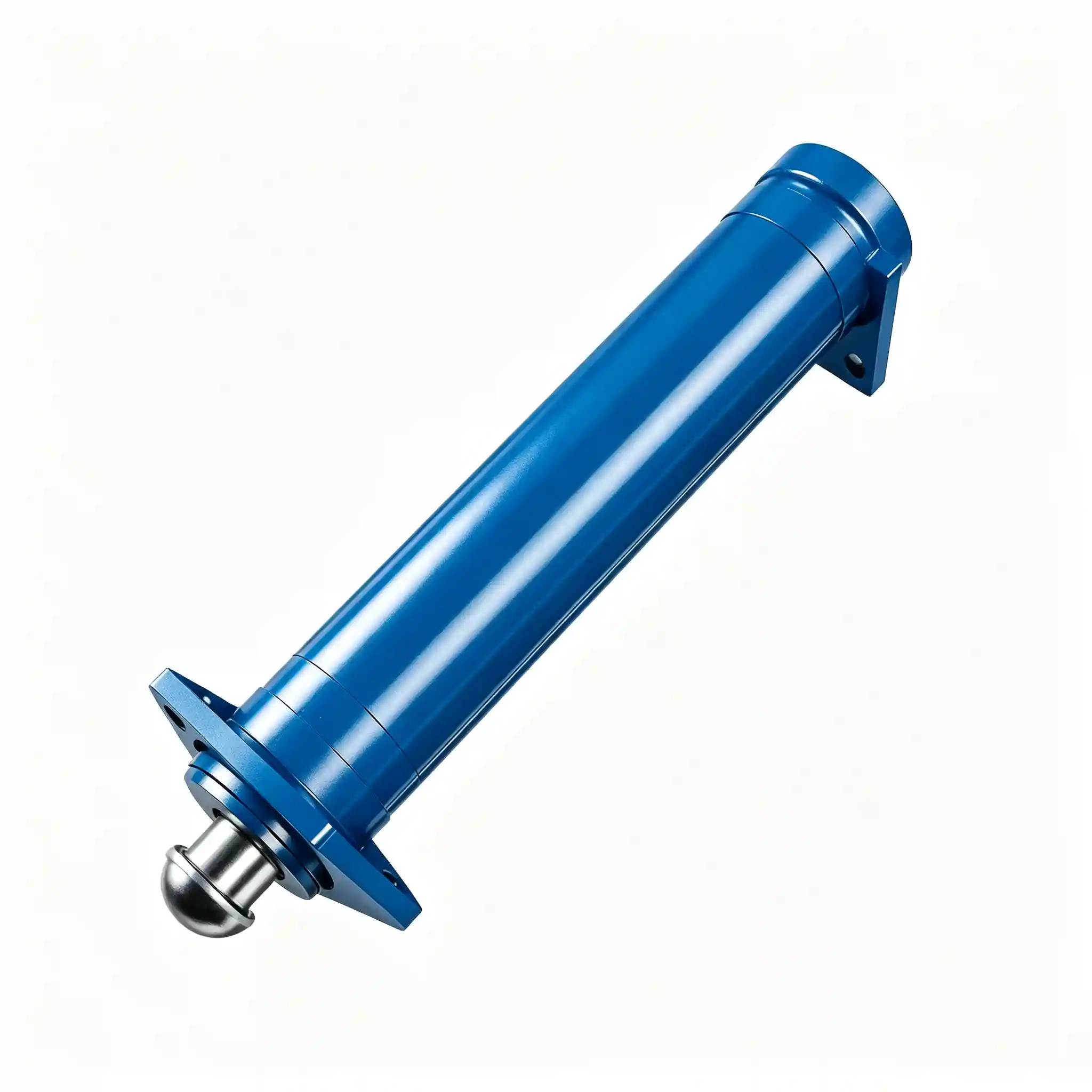
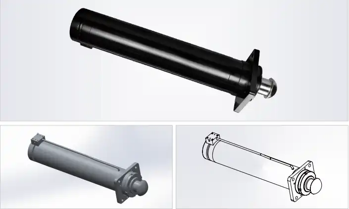
Model: HCYY11112023
Crane Outrigger Jack Hydraulic Cylinder
The crane outrigger jack hydraulic cylinder HCYY11112023 is the vertical actuator that drives the outrigger pad into the ground, lifts the crane chassis clear of its suspension, and holds the entire loaded structure stationary throughout the lift cycle. With a Φ140mm bore, a 640mm stroke, and the highest working pressure in this outrigger series at 30MPa, this cylinder operates under sustained compressive load — not just during deployment, but for the entire duration of every crane operation.
Key Specifications at a Glance
- Bore × Rod × Stroke: Φ140 × Φ120 × 640 mm
- Working Pressure: 30 MPa
- Max Withstand Pressure: 40 MPa
- Installation Distance: 983 mm
- Weight: 123 kg
What the Vertical Jack Cylinder for Crane Outrigger Actually Carries During a Lift
The outrigger extension cylinder (HCYY11112022) deploys the beam horizontally. The outrigger jack cylinder does the structurally critical work that follows: it extends vertically downward to press the outrigger pad against the ground, continues extending until the crane’s tyres are lifted clear of the surface, and then holds that position — under the combined weight of the crane chassis, counterweight, boom assembly, and suspended load — for as long as the lift takes.
This sustained static load under working pressure is what differentiates the jack cylinder’s duty from the extension cylinder’s duty. The extension cylinder cycles once to deploy and once to retract — its working time is measured in seconds per shift. The jack cylinder extends once, then holds position under full load pressure for minutes or hours depending on the lift operation. Seal integrity under prolonged static pressure loading is the primary engineering challenge in outrigger jack cylinder design.
At 30MPa working pressure across a Φ140mm bore, the HCYY11112023 generates approximately 462 kN of vertical push force — approximately 47 tonnes-force per jack cylinder. With four jack cylinders deployed simultaneously, the total vertical support capacity reaches approximately 185 tonnes, sufficient for cranes in the 50–160 tonne class depending on chassis geometry and load distribution. The 40MPa maximum withstand pressure — a 1.33× safety factor over rated working pressure — ensures the cylinder barrel and end closures remain structurally sound under the ground reaction force peaks that occur on uneven or compressible ground surfaces.
The Φ120mm rod diameter relative to the Φ140mm bore gives a rod-to-bore ratio of 86% — among the highest of any cylinder in this product range. This ratio reflects the compressive loading reality: a jack cylinder rod is essentially a vertical column in compression, and its buckling resistance must be sized for the worst-case condition where the crane is tilted on uneven ground and the jack load is not perfectly axial.
Installation Position Diagram — HCYY11112021 / 22 / 23 on Crane
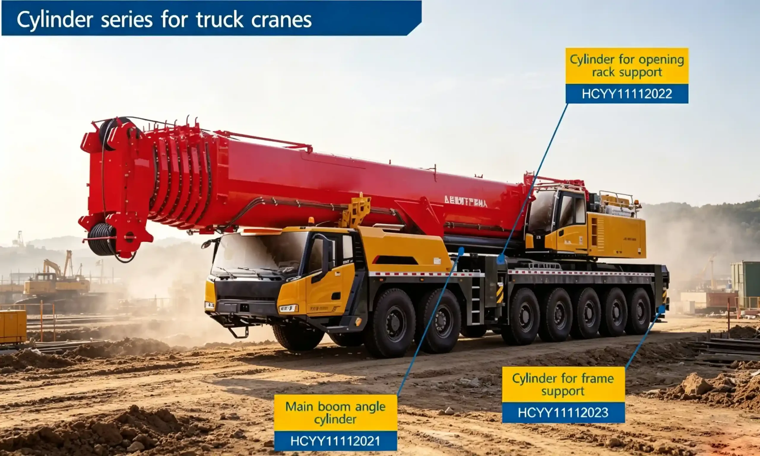
Diagram showing the vertical mounting position of the outrigger jack cylinder (HCYY11112023) relative to the main boom lift cylinder (HCYY11112021) and outrigger extension cylinder (HCYY11112022) within the crane structure.
Full Technical Specifications for the HCYY11112023 Hydraulic Jack Cylinder for Crane Stabilizer Pad
The specification of a jack cylinder must be read differently from a motion-generating cylinder. Parameters like bore area, working pressure, and rod-to-bore ratio carry particular weight because the cylinder spends most of its life holding a static load, not moving.
| Parameter | Value | Engineering Significance |
|---|---|---|
| Model | HCYY11112023 | Unique product identifier for procurement and MRO spare part orders. |
| Specifications | Φ140 × Φ120 × 640 mm | Bore × Rod × Stroke. The Φ120mm rod is 86% of bore diameter — the highest rod-to-bore ratio in the outrigger cylinder set, reflecting compressive column loading demands. |
| Working Pressure | 30 MPa | Highest working pressure in the outrigger series. At Φ140mm bore (effective area ≈ 15,394 mm²), this produces approximately 462 kN vertical push force — approximately 47 tonnes-force per jack position. |
| Max Withstand Pressure | 40 MPa | The highest proof pressure in this cylinder series. Provides structural margin against dynamic ground reaction spikes on compressible or uneven surfaces during lift operations. |
| Stroke | 640 mm | Vertical travel distance from pad contact with ground to maximum chassis lift height. Determines the maximum ground clearance achievable and the maximum terrain height variation the crane can compensate for during levelling. |
| Installation Distance | 983 mm | Pin-to-pin retracted length. Sets the vertical packaging envelope within the outrigger box beam and determines the available space for internal hose routing. |
| Weight | 123 kg | Consistent with the structural requirements of a Φ140mm bore cylinder carrying sustained 30MPa load. Heavier than the extension cylinder (48kg) due to increased wall thickness requirements at higher working pressure. |
Why the 30MPa Working Pressure and 40MPa Withstand Rating Define Safe Crane Levelling Operations
Among the seven crane hydraulic cylinders in this series, the HCYY11112023 carries the highest working pressure at 30MPa and the highest proof test pressure at 40MPa. This is not coincidental — it reflects the load conditions that an outrigger jack cylinder uniquely faces.
When a crane is set up on ground that is not perfectly flat, the four jack cylinders do not share the load equally. Ground settlement under one pad, a rock under another, or a subtle slope in the terrain means that two or even one jack cylinder may be carrying a disproportionately large fraction of the total crane weight. In the worst case — one pad settling on soft ground while the crane is mid-lift — the remaining jack cylinders must absorb the redistributed load. The 30MPa working pressure rating accounts for these load redistribution scenarios rather than assuming perfectly equal load sharing across all four jacks.
The 40MPa maximum withstand pressure — a 33% margin above working pressure — specifically addresses the ground reaction force spikes that occur when a pad settles suddenly into soft ground, transferring load abruptly to the adjacent jacks. A cylinder rated only to its working pressure with no proof margin would be structurally at risk under these transient overload conditions. The 40MPa rating means the barrel wall, welds, and end closure threads have been designed, manufactured, and tested to sustain that pressure without permanent deformation.
The 640mm stroke provides adequate height adjustment range for most civil construction and industrial lift scenarios, while keeping the retracted installation distance (983mm) manageable within the vertical space available in the outrigger beam’s lower section.
Static Load Holding and Drift Prevention in Vertical Jack Cylinders for Mobile Crane Outrigger Systems
The most safety-critical performance requirement for a crane outrigger jack cylinder is not its extension force or its cycle speed — it is its ability to hold position without drift under sustained load pressure when the control valve is in neutral.
In a well-maintained jack cylinder, the piston seal and rod seal system prevents internal leakage past the piston (which would allow the cylinder to slowly retract under load) and external leakage past the rod seal (which would be visible as oil weeping around the rod). Either form of leakage in a loaded jack cylinder is a safety issue, not merely a maintenance inconvenience. Slow retraction under load means the crane chassis gradually descends, changing the boom geometry, load radius, and — critically — the load on the other three jack cylinders.
The HCYY11112023’s seal system is designed for sustained static load. The piston seal uses a configuration that generates higher sealing force under higher differential pressure — so the seal’s effectiveness actually improves as the load on the jack increases. This pressure-energised sealing behaviour is the correct approach for jack cylinder applications and is notably different from the seal configurations appropriate for motion-generating cylinders where low breakout friction is the priority.
It is important to note that the cylinder’s internal seal system is the last line of defence against drift — the primary line of defence should always be the crane’s hydraulic lock valves (counterbalance valves or pilot-operated check valves fitted in the outrigger circuit). A cylinder with degraded seals relying on hydraulic lock valves alone for load holding is operating outside its intended safety architecture.
Where Crane Stabilizer Jack Cylinders Are Deployed — Typical Use Cases and Operating Environments
The HCYY11112023 is applicable to any mobile crane that uses a vertical hydraulic jack cylinder at each outrigger corner. Typical deployment scenarios include:
- Truck-mounted cranes (50t–160t class): Four jack cylinders deploy simultaneously and must level the crane on variable ground. Load per jack in this class ranges from 30 to 80 tonnes depending on counterweight configuration and load radius.
- All-terrain cranes on construction sites: Ground conditions range from compacted gravel to soft fill — each surface type generates different dynamic ground reaction characteristics that the jack cylinder and its circuit must accommodate.
- Industrial plant maintenance cranes: In steel mills, chemical plants, and power stations where cranes may remain deployed for extended periods (hours to days) during planned maintenance shutdowns. Sustained static load holding without drift is the primary requirement.
- Bridge and infrastructure construction: Where cranes operate on temporary roadways, crane mats, or engineered fill where ground bearing capacity is calculated but dynamic settlement is still possible.
- OEM crane manufacturing: First-fit supply to crane builders requiring consistent dimensional and pressure-holding performance across production batches.
- Fleet MRO: Replacement of jack cylinders showing signs of drift, external leakage, or physical damage to the rod caused by off-axis loading during setup on uneven ground.
Construction Standards That Support Long-Term Static Load Performance in Vertical Crane Jack Cylinders
For a jack cylinder that must hold a 40–80 tonne load without drift for hours at a time, material and manufacturing standards are not interchangeable with lower-grade alternatives. The following details define the build quality of the HCYY11112023.
Cylinder Barrel Wall Thickness
At 30MPa working pressure with a Φ140mm bore, barrel wall thickness is calculated per Lamé’s equation with a burst safety factor applied. Material is seamless structural steel (20# or equivalent) with certified mechanical properties — yield strength and tensile strength are both verified on heat certificate, not assumed from material grade alone.
Φ120mm Piston Rod
The large-diameter rod — 86% of bore — is hard chrome plated on 45# or 42CrMo steel. The 42CrMo option provides higher yield strength for applications where eccentric loading during crane setup creates bending moments in the rod. Rod straightness is verified along the full length post-machining: maximum runout 0.05mm per 300mm.
Piston Seal Assembly
A pressure-energised seal configuration is used at the piston — as cylinder pressure increases under load, the seal contact force increases proportionally. This means the seal is at its most effective precisely when the load is at its highest, which is the correct response characteristic for a jack cylinder application.
Gland and Rod Seal
The rod seal gland is a precision-machined assembly with a primary polyurethane seal, backup PTFE ring, and heavy-duty wiper. At 30MPa, the gland thread engagement depth is sized to prevent thread pullout under the axial force generated by rod seal friction during extension — a calculation often overlooked in jack cylinder gland design.
Outrigger Pad Interface
The rod end spherical or flat pad interface allows angular articulation to accommodate ground surface irregularities without transmitting bending moment into the rod. The pad socket is heat-treated for wear resistance at the contact face, which sees very high local bearing stress from the crane’s point load onto the outrigger mat or ground surface.
Pressure Testing Protocol
Each cylinder is tested at 40MPa — the full maximum withstand pressure — with a minimum 5-minute hold. The test must demonstrate zero internal leakage (no drift in extended position under pressure) and zero external leakage. Test records are retained and available on request for quality audit purposes.
Ordering and Procurement Checklist for Crane Outrigger Jack Cylinder Replacement or OEM Supply
Outrigger jack cylinders are safety-critical components. Before finalising a procurement order, confirm the following parameters to ensure dimensional and functional compatibility with your crane:
- Installation distance at retraction (983mm): This is the most common source of fitment errors. Measure the existing cylinder pin-to-pin at full retraction — if the replacement cylinder is longer or shorter, the outrigger beam geometry and hose routing will be affected.
- Pad interface type: Flat pad, spherical knuckle, or fixed eye rod end. The interface must allow adequate angular articulation to handle uneven ground without creating bending load in the rod.
- Head end mounting: Trunnion, clevis, or flange mount at the cylinder head. Confirm bore diameter, pin width, and whether a spherical bearing is fitted in the pin eye.
- Port position and specification: On a vertically-mounted jack cylinder, port position determines whether oil drains correctly on retraction and whether the hose connection creates any strain on the fitting. Specify port location (head end / rod end) and thread type.
- Seal material: Standard polyurethane/PTFE for mineral oil. Fire-resistant fluid applications require Viton (FKM) seals — specify fluid type at time of order.
- Crane model, rated capacity, and outrigger position (front/rear): Front and rear outrigger jack cylinders on the same crane may have different specifications — confirm which position you are sourcing for.
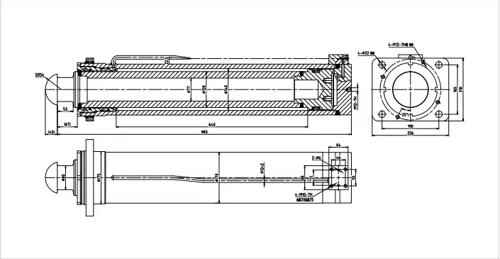
HCYY11112023 CAD Drawing Reference
Full-dimension CAD drawing available in DXF and PDF format. Provide your crane model and installation constraints to receive the dimensional verification package.
Frequently Asked Questions — HCYY11112023 Crane Outrigger Jack Hydraulic Cylinder
B2B Procurement & OEM Supply
Specify or Source the HCYY11112023 for Your Crane Fleet
Provide your crane model, current jack cylinder measurements, operating fluid type, and required quantity. We will confirm compatibility, supply a CAD drawing for engineering sign-off, and issue a formal quotation within 24–48 business hours. Matched sets of four jack cylinders can be supplied from the same production batch.