
Standard worm gearboxes carry 15–20 arc-minutes of backlash — the angular play at the output before the gear pair makes firm contact under reversal. For a speed reducer driving a conveyor or mixer, that play is inconsequential. For a servo motor driving a CNC rotary table, a robot joint, or a precision automation axis, it means position error that accumulates with every reversal and cannot be corrected by even the most sophisticated servo controller. The low backlash right angle worm gearbox exists specifically to solve this problem.
This page covers the full technical specification of EPG Canada’s Low Backlash Right Angle Servo Worm Gearbox series: backlash grades, frame sizes, torque and speed ratings, gear pair design, motor interface, and output configurations. For application guidance covering CNC, robotics, and precision automation, see our Servo Worm Gearbox Applications guide.
Why a Standard Worm Gearbox Cannot Be Used with a Servo Motor
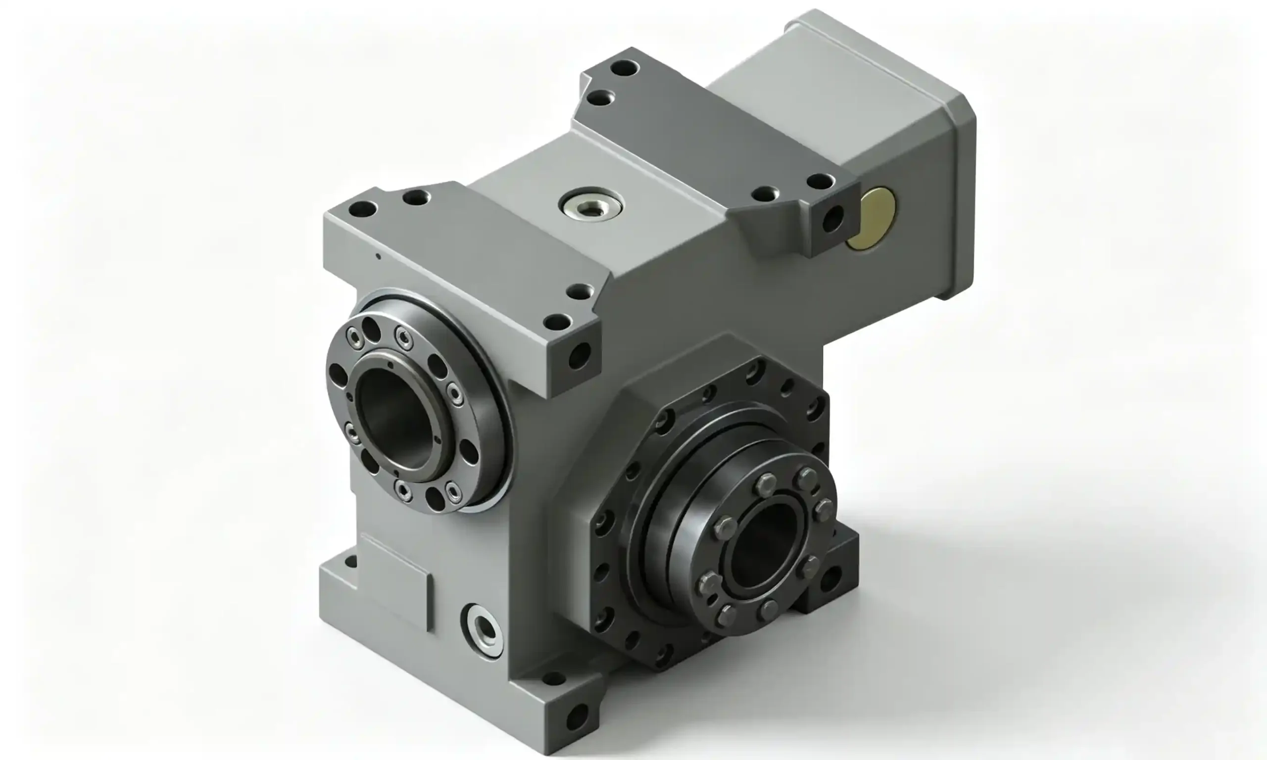
Precision servo worm gearhead — three-bearing worm shaft, >90% tooth contact, and a universal servo motor adapter as standard
Servo motor positioning relies on the controller’s ability to command an exact output position by counting encoder pulses at the motor. Backlash — the angular play between worm and wheel — is a dead zone that is invisible to the encoder but real at the output. A standard worm gearbox with 15 arc-minutes of backlash on a 50:1 drive produces approximately 0.3° of positioning uncertainty at the output shaft on every reversal. On a CNC rotary table or robotic joint, that is the difference between a part being in tolerance and being scrapped.
Critical Engineering Note
Adapting a standard worm gearbox to a servo drive does not solve the backlash problem. The servo controller cannot compensate for mechanical play — it can only act on what the encoder reports. The backlash between worm and wheel occurs downstream of the encoder and is mechanically invisible to the controller. Only a purpose-designed precision servo worm gearbox, engineered with controlled low-backlash gear contact, is appropriate for servo motor applications requiring position accuracy.
Four design differences separate a precision servo worm gearbox from a standard industrial worm reducer at the same frame size: controlled tooth contact geometry (90–95% contact versus 60–70% on standard worm gears), a precision bronze alloy worm wheel that maintains contact geometry as wear accumulates, a three-bearing worm shaft arrangement that maintains preload across temperature changes, and a torsionally rigid input coupling that eliminates coupling wind-up from the positioning error budget.
Three Backlash Precision Grades: Matching Grade to Application
Three precision grades are available, allowing engineers to specify exactly the backlash level their application requires — rather than defaulting to the tightest (and most expensive) grade across the board. Over-specifying backlash grade adds cost without adding positioning benefit for the application in question.
Backlash vs. accuracy: Backlash is a mechanical property of the gear pair under no-load, quasi-static reversal conditions. Actual servo positioning accuracy depends also on encoder resolution, servo gain settings, mechanical compliance of the overall drive train, and thermal effects. Specifying the Expert backlash grade does not by itself guarantee sub-arc-minute positioning accuracy — the entire drive train from motor to load must be analysed. Contact our technical team for a full positioning accuracy budget review if your application requires sub-arc-minute output accuracy.
Technical Specifications by Frame Size
Eight frame sizes cover input torques from miniature servo drives up to heavy precision automation axes. All frame sizes are available in all three backlash grades.
| Size | Max Cont. Output Torque (Nm) | Max Input Speed (RPM) | Ratio Range | Output Shaft Dia. (mm) | Noise Level (dB) |
|---|---|---|---|---|---|
| S1 | 10 | 6,000 | 5 – 90:1 | 12 | <50 dB |
| S2 | 25 | 6,000 | 5 – 90:1 | 16 | <50 dB |
| S3 | 70 | 5,000 | 5 – 90:1 | 20 | <52 dB |
| S4 | 175 | 4,500 | 5 – 90:1 | 28 | <55 dB |
| S5 | 400 | 4,000 | 5 – 90:1 | 38 | <55 dB |
| S6 | 750 | 3,500 | 5 – 90:1 | 48 | <55 dB |
| S7 | 1,200 | 3,000 | 5 – 90:1 | 60 | <55 dB |
| S8 | 1,500 | 2,500 | 5 – 90:1 | 70 | <55 dB |
* Continuous output torque values are at rated input speed and standard operating temperature. Peak torque is typically 2× continuous. Maximum input speed decreases at larger frame sizes due to bearing and sealing constraints. All specifications are at 20°C ambient — contact our team for thermal derating at higher ambient temperatures.
Standard Ratio Steps Available (All Frame Sizes)
7.5:1
10:1
15:1
20:1
25:1
30:1
40:1
50:1
60:1
75:1
90:1
A single stage at 90:1 achieves a higher reduction than most planetary gearboxes in the same frame footprint, at significantly lower cost — one of the key advantages of the right-angle worm format in precision automation.
Precision Worm and Wheel Design: How Low Backlash Is Achieved
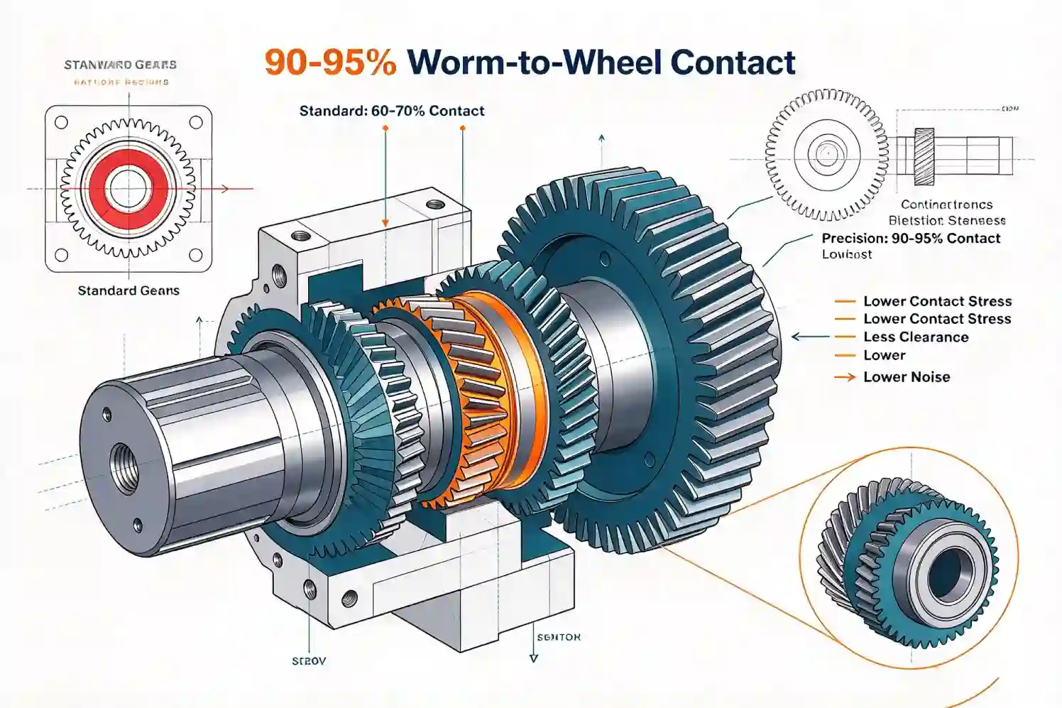
90–95% Worm-to-Wheel Contact
Standard worm gears achieve 60–70% contact area. Precision servo worm gears are ground to achieve 90–95% contact — distributing load across a larger area, reducing contact stress, and eliminating the clearance zones that create backlash on standard worm pairs. The higher contact ratio also contributes directly to lower noise output.
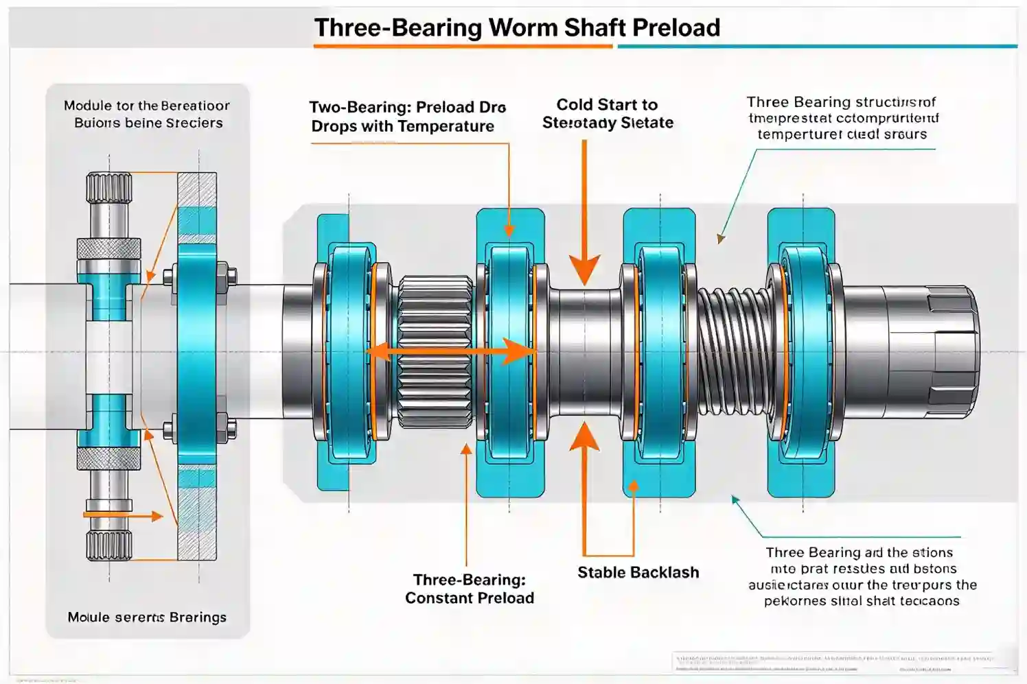
Three-Bearing Worm Shaft Preload
Two-bearing worm shaft arrangements lose preload as the gearbox warms from cold start to operating temperature — the worm shaft grows axially, reducing contact pressure and increasing effective backlash. The three-bearing arrangement used here maintains constant preload across the full operating temperature range, so backlash remains constant from cold start to steady state.
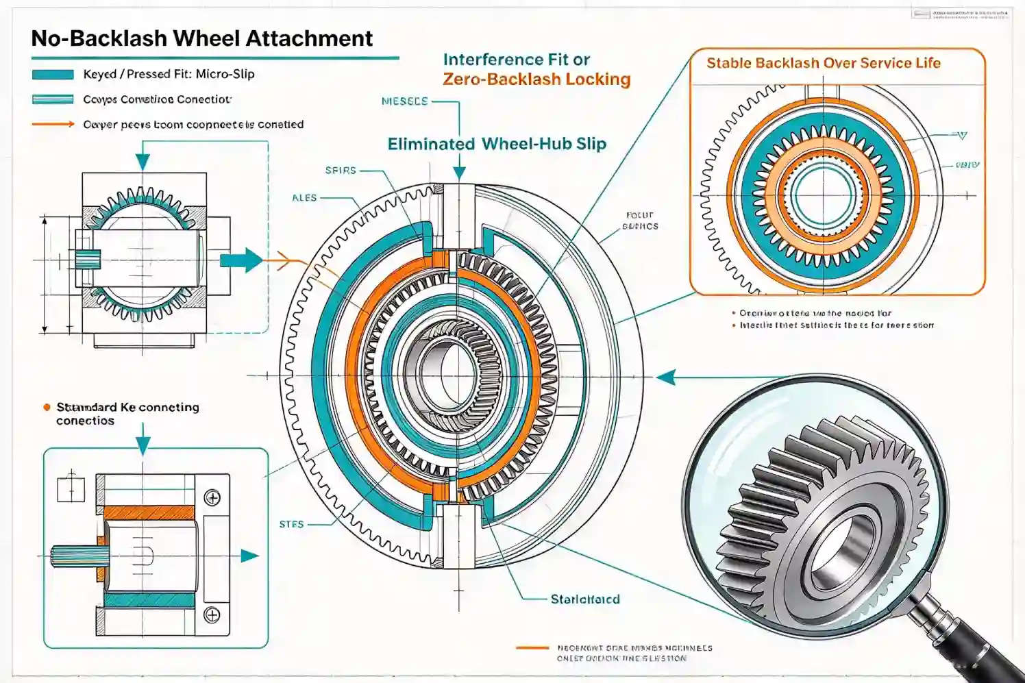
No-Backlash Wheel Attachment
Standard worm wheels are attached to their hub via a key or pressed fit — both methods allow micro-slip under load reversals that adds to measured backlash over time. Precision servo worm wheels use an interference-fit or zero-backlash locking assembly method that eliminates the slip at the wheel-hub interface, keeping backlash stable over the service life.
Housing: Aluminum-Magnesium Alloy for Rigidity Without Mass
Precision servo gearboxes are frequently mounted at the end of a robot arm, on a moving gantry, or in a confined machine envelope where mass and moment of inertia matter as much as stiffness. The one-piece aluminum-magnesium alloy (Al-Mg) housing used across all frame sizes provides the combination required:
High Specific Stiffness
Al-Mg alloy has a higher stiffness-to-weight ratio than standard aluminum die-cast alloys — the housing maintains bearing bore alignment under the worm gear forces without adding unnecessary mass to the drive system.
One-Piece Construction
The housing is cast and machined as a single piece — no split-line joints that can flex under load and create micro-movement at the bearing bores. Consistent geometry maintains gear pair alignment across the operating load range.
Thermal Stability
Al-Mg alloy’s thermal expansion coefficient is well-characterised and consistent — enabling the three-bearing preload system to be designed for constant contact force across the specified operating temperature range (typically -10°C to +60°C).
Corrosion Resistance
Natural aluminum oxide layer provides corrosion resistance without the mass of cast iron — suitable for clean-room, pharmaceutical, and food-adjacent environments where the gearbox must remain clean and rust-free.
Servo Motor Interface: Universal Adapter and Torsionally Rigid Coupling
The motor connection is a critical element of the precision drive chain — any coupling wind-up or motor adapter flex translates directly into positioning error at the output. Two standard elements address this:
Universal Servo Motor Adapter
A precision-machined aluminum adapter ring is supplied with each gearbox, matched to the motor frame and flange type specified at order. Compatible with all major servo motor brands (Siemens, Fanuc, Yaskawa, Mitsubishi, Bosch Rexroth, Allen-Bradley, and equivalent). Specify your servo motor brand and frame size when ordering — no custom machining is required at installation.
Adapter supplied with gearbox — no additional sourcing required.
Torsionally Rigid Flexible Coupling
A spider jaw coupling (or equivalent torsionally rigid coupling) is included as standard. It connects the servo motor shaft to the worm input with near-zero backlash and near-zero torsional wind-up — critical because coupling torsional compliance adds to the effective positioning error of the drive chain. The coupling also accommodates the minor parallel and angular misalignment between motor and gearbox shaft centres without transmitting bending loads into the motor bearings.
No separate coupling purchase required for standard motor frame sizes.
Output Shaft and Flange Configurations
| Output Configuration | Description | Best For |
|---|---|---|
| Single Solid Shaft (keyed) | Standard keyed output shaft — connects to the load via a coupling or direct keyed bore | Rotary table inputs, gantry drives, general servo positioning |
| Double Solid Shaft | Shaft extends from both sides — drive two loads or mount encoder on the second shaft end | Dual-load drives; encoder feedback from the output shaft side |
| Hollow Bore (keyed or shrink disc) | Hollow output bore slides directly onto the driven shaft — eliminates coupling and reduces assembly length | Robot joint drives; compact automation heads; shaft-mounted axes |
| Rotary Output Flange | Precision-ground output flange with bolt circle for direct connection to the load plate or rotary table | CNC rotary tables; trunnion axes; direct-mount precision positioning stages |
Request a Precision Servo Worm Gearbox Quotation
Provide your servo motor brand and frame, required ratio, output torque, backlash grade, and output configuration. We will return a confirmed model code, dimensional drawing, and pricing within 24 hours.