Descrição
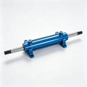
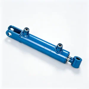
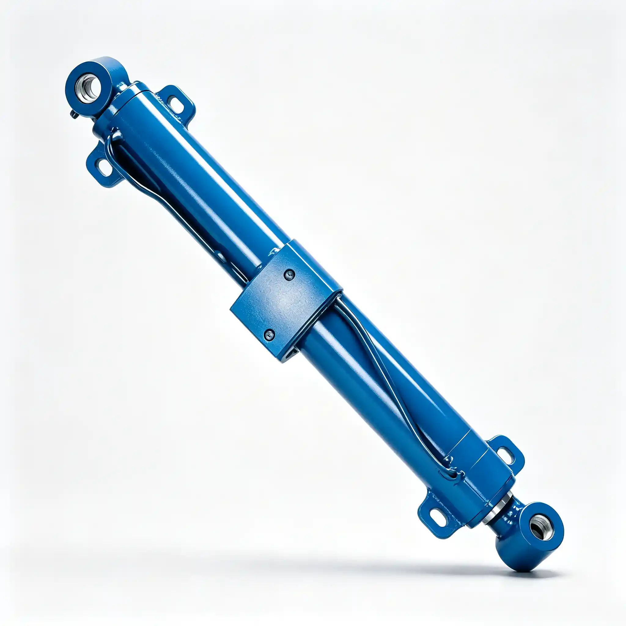
HCYY11112012 — Aerial Lift Steering Hydraulic Cylinder | Φ63×Φ35×320, 21 MPa
The HCYY11112012 is the steering cylinder for large-format boom-type aerial work platforms — the actuator that controls drive-wheel direction on heavy diesel telescopic and articulating boom lifts. With a Φ63 mm bore, 320 mm stroke, and 21 MPa working pressure, it is the highest-pressure and longest-stroke steering cylinder in this product line, purpose-built for machines where steering axle loads are too high for the compact low-pressure steering actuators used on electric or smaller platforms.
A steering cylinder failure is categorically different from a lifting or leveling cylinder failure. When a lifting cylinder loses sealing integrity, the boom drifts slowly — the operator has time to notice and respond. When a steering cylinder fails under load — rod seal blowout, port fitting fracture, or sudden internal bypass — directional control is lost immediately. On a 15,000–25,000 kg boom lift traveling on a construction site, sudden loss of steering is a serious safety event. This is not a worst-case scenario built for a product page — it is the reason steering cylinder pressure ratings, proof test standards, and installation distance precision are held to the same engineering discipline as primary structural components.
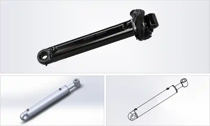
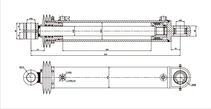
Technical Specifications — High-Pressure Aerial Lift Steering Cylinder, Φ63 Bore, 21 MPa
| Parameter | Value | What It Means in Practice |
|---|---|---|
| Model | HCY11112012 | OEM part reference |
| Bore × Rod × Stroke | Φ63 × Φ35 × 320 mm | Rod-to-bore ratio 0.556; extension force ≈ 65.7 kN, retraction force ≈ 45.6 kN at 21 MPa |
| Working Pressure | 21 MPa | Highest steering pressure in this range — 5.2× the force output of the 10 MPa electric platform version |
| Max Withstand Pressure | 32 MPa | 1.52× working pressure; absorbs pressure spikes from wheel impact on obstacles during travel |
| Stroke | 320 mm | Longest steering stroke in this range — corresponds to wide-track large axle geometry requiring greater tie rod travel |
| Installation Distance | 540 mm | Pin-to-pin retracted length; determines steering geometry — an error here changes effective Ackermann angle |
| Weight | 13 kg | Single-person lift is feasible but awkward in confined axle access; two people recommended for pin alignment |
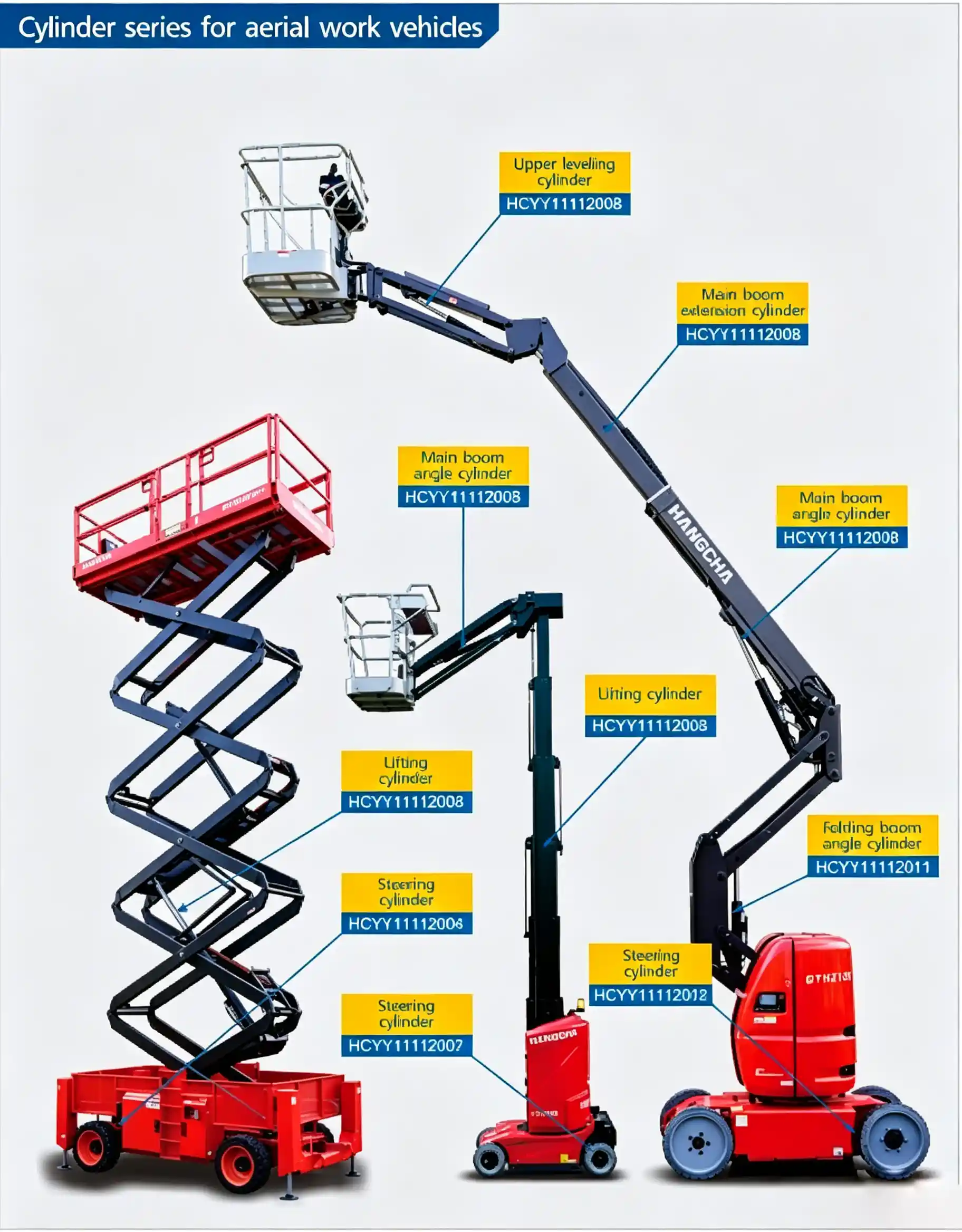
Installation position reference — HCYY11112012 steering cylinder in boom lift axle hydraulic layout
Why Large Boom Lift Steering Cylinders Run at 21 MPa When Electric Platforms Use 10 MPa
The steering force required to turn a drive axle is not just a function of axle weight — it also depends on tire size and inflation pressure, surface friction coefficient, turning speed, and the moment arm from the king-pin axis to the tire contact patch center. Large diesel boom lifts use wider, higher-load-capacity tires than electric indoor machines, which increases the pneumatic trail and the self-aligning torque the steering cylinder must overcome.
On a large rough-terrain machine with 355/55 R20 or similar tires at 8–10 bar inflation, the steering moment can exceed 4,500 N·m per wheel when the machine is stationary on a firm surface with full counterweight and a loaded platform. With a typical steering knuckle arm length of 120–150 mm, the cylinder must generate a tie-rod force of 30,000–37,500 N per wheel just to initiate a static steer. With two wheels being steered simultaneously through a common cylinder, the combined demand approaches the 65.7 kN extension force the HCYY11112012 delivers at 21 MPa.
The 10 MPa version (HCYY11112007) produces approximately 12.6 kN — adequate for a compact electric machine on smooth indoor floors with small low-pressure tires, but less than 20% of what a large rough-terrain machine needs for a static steer. Using the wrong pressure-rated steering cylinder on a large machine does not produce a safety warning — it produces a machine that either cannot complete a full steering lock on firm ground or constantly hits the steering relief valve, overheating the hydraulic circuit and accelerating pump wear.
320 mm Stroke and the Steering Geometry It Controls: Ackermann Angle and Turning Radius
The 320 mm stroke of the HCYY11112012 is 2.56× longer than the 125 mm stroke of the HCYY11112004. This is not because the large machine needs proportionally more wheel angle — most boom lifts steer to ±55–60° wheel angle regardless of size. The longer stroke exists because large axles have longer knuckle arms, and the cylinder attaches further from the king-pin centerline to generate the required torque at lower tie-rod force per degree of travel.
The relationship between cylinder stroke and wheel turn angle is determined by the knuckle arm length and the cylinder attachment geometry. For a knuckle arm of 180 mm (typical of a large boom lift axle), 320 mm of cylinder travel produces approximately 62° of wheel turn from lock to lock — which corresponds to a minimum turning radius of roughly 3.5–4.0 meters for a machine with a 2.5 m wheelbase. This is the tightest turn radius achievable at full steering lock on such a machine.
The 540 mm installation distance places the cylinder in a specific geometric relationship with the axle housing and the tie rod attachment point. Changing the installation distance by even 10–15 mm shifts the cylinder’s mid-travel position relative to the straight-ahead wheel alignment — the machine will not track straight without a steering alignment correction, and the effective lock-to-lock travel will be unequal left versus right.
Road Shock, Pressure Spikes, and Why Steering Cylinders Need a Higher Safety Margin Than Their Rated Pressure Implies
The 32 MPa maximum withstand pressure on a 21 MPa working-pressure cylinder gives a 1.52× ratio — but the practical case for this margin is more specific than a generic safety factor. Steering cylinders on rough-terrain boom lifts are exposed to wheel impact loads that create sudden pressure spikes in the hydraulic steering circuit.
When a front drive wheel hits a rock or a concrete edge at travel speed, the impact force transfers through the tire, into the axle, and along the steering linkage to the cylinder rod. The cylinder cannot instantaneously relieve this force through the hydraulic circuit — the steering control valve is a metering device, not an instantaneous pressure relief. For the brief duration of the impact event — typically 20–50 milliseconds — the cylinder port pressure can spike well above the steering circuit relief valve setting. The 32 MPa rating ensures the cylinder barrel, port threads, and welds absorb this spike without yielding or cracking.
The steering circuit relief valve is typically set at 22–24 MPa on systems using this cylinder — intentionally just above the 21 MPa working pressure to allow full-force steering without relief valve intervention during normal operation, while providing circuit protection before the 32 MPa cylinder maximum is approached. If the relief valve is found set below 21 MPa on a machine using the HCYY11112012, the system cannot develop full steering force — a symptom that appears as heavy or sluggish steering on firm ground that disappears on softer surfaces.
The Φ35 mm rod diameter is sized with this impact loading in mind. At the moment of wheel impact, the rod is under combined tension (from the tie rod pulling) and bending (from the off-axis impact force). The Φ35 mm cross section provides adequate bending resistance at the 320 mm stroke length, where the rod is at maximum exposure between the guide bushing and the rod end pin.
Steering Cylinder Failure Modes on Heavy Boom Lifts: What to Watch For and When to Replace
Steering cylinder failure on a large boom lift does not always announce itself with an external oil leak. The failure modes range from immediately obvious to deceptively subtle:
- Rod seal weep at 21 MPa — the most visible failure. At this pressure, a degraded rod seal will progress from a thin oil film to an active drip within days of first appearing. Do not operate the machine once a weep is observed — at 21 MPa, a seal that is weeping is one impact event away from becoming an active leak that empties the steering circuit. Take the machine out of service and replace the cylinder.
- Steering pull to one side — if the machine consistently pulls left or right during travel on a level surface with the steering released, and the tire pressures are correct, the steering cylinder may have developed internal bypass. The high-pressure side fluid is crossing the piston to the low-pressure side, creating a net force that biases the wheel angle. This is not yet a safety emergency on a stationary machine, but it will worsen and the cylinder must be inspected.
- Excessive steering wheel play or sluggish response — if the machine uses a hydraulic steering handwheel, air in the steering circuit from a partial seal failure produces compressibility and a spongey, delayed response. On machines with joystick-controlled steering, the symptom is a travel direction that takes 0.5–1 second to respond to input rather than the immediate response of a properly functioning circuit.
- Chrome rod damage after wheel impact — inspect the rod visually after any significant obstacle impact during travel. A scored or dented rod will destroy the rod seal within hours of resumed operation at 21 MPa. If the rod surface is damaged in the active travel zone — any part of the 320 mm stroke length — replace the cylinder rather than attempting a reseal with a damaged rod.
- Port fitting or hose connection weeping — at 21 MPa, port thread integrity and hose end fitting condition are critical. Check all connections at the steering cylinder for signs of weeping at every service interval. A port fitting that is weeping under 21 MPa has a degraded thread seal that will fail under the next significant pressure spike — replace the fitting before the cylinder itself becomes collateral damage from a sudden fitting failure.
Three Steering Cylinders, Three Different Machines: How to Select the Right One
This product line includes three distinct steering cylinders. Selecting the wrong one based on visual similarity or approximate dimensions is a common and costly error in aftermarket replacement sourcing:
| Model | Bore × Rod | Pressure | Stroke | Installation Dist. | Platform Type |
|---|---|---|---|---|---|
| HCYY11112004 | Φ40 × Φ20 | 20 MPa | 125 mm | 400 mm | Compact diesel / standard pressure |
| HCYY11112007 | Φ40 × Φ25 (dual) | 10 MPa | 100 × 2 mm | 645 mm | Electric indoor / low-pressure circuit |
| HCYY11112012 | Φ63 × Φ35 | 21 MPa | 320 mm | 540 mm | Large diesel rough-terrain / high-force |
The HCYY11112004 and HCYY11112012 look superficially similar — both are single-rod steering cylinders at similar working pressures. The critical differences are bore diameter (Φ40 vs Φ63), stroke (125 mm vs 320 mm), and installation distance (400 mm vs 540 mm). Fitting a Φ40 bore cylinder to a machine designed for a Φ63 bore will reduce available steering force by 57% — the machine will steer adequately on soft ground but fail to complete full lock on firm surfaces, which will be interpreted as a pump or valve fault until the cylinder specification is checked.
Installation Procedure and Circuit Bleeding for the HCYY11112012
The 540 mm installation distance must be matched to the steering linkage’s pin-to-pin dimension with the wheels in the straight-ahead position. Install the cylinder at neutral (wheels straight), connect both hydraulic ports, then verify full lock travel is equal left and right before tightening the pin retaining hardware permanently. Unequal lock-to-lock travel after installation indicates either an installation distance mismatch or an offset neutral position — both must be corrected before the machine returns to service.
Bleed the steering circuit with the machine stationary and all weight on the drive wheels. Cycle lock-to-lock slowly 5–8 times at low engine speed (or low pump speed for electric drive) to purge trapped air. Air in a 21 MPa steering circuit compresses measurably and produces a noticeably spongey steering response — if the sponge feeling has not cleared after 8 cycles, check for a loose port fitting admitting air on the low-pressure side during retraction.
Platform Types and Operating Environments for the HCYY11112012
- Large diesel telescopic boom lifts (18–43 m working height) — rear-axle or front-axle steering on machines with wide-track heavy-duty axles where the Φ40 bore cylinders used on smaller platforms cannot meet the steering force requirement on firm ground.
- Large articulating boom lifts with four-wheel steering — platforms using independent rear-axle steering for crab-steering or coordinated four-wheel-steer mode, where each rear wheel has its own HCYY11112012, requiring matched cylinders for symmetrical steering response.
- Rough-terrain construction platforms — machines working on unpaved surfaces, quarry floors, and construction sites where wheel impact loads from uneven ground are a routine operational condition, demanding the 32 MPa withstand rating over repeated impact events.
- High-capacity platforms (rated ≥ 300 kg platform load) — heavier machines with larger counterweights and wider stances require proportionally heavier axle components and higher steering forces to achieve rated maneuverability at full load.
- Rental fleet aftermarket replacement — high-utilization rental machines accumulating 1,500+ hours per year in outdoor construction applications where steering cylinder rod seals are typically on a 1,000–1,500 hour replacement schedule due to the combination of 21 MPa operating pressure and contamination exposure.
Request HCYY11112012 — Steering Cylinder with Full Pressure Certification
We supply the HCYY11112012 to boom lift manufacturers, authorized service centers, and rental fleet operators globally. Given the safety-critical nature of steering cylinder supply, we include full pressure test documentation, dimensional verification, and hydraulic fluid compatibility data as standard with every order — not on request.
- 32 MPa hydrostatic proof test certificate per unit
- Full stroke function test — extension and retraction verified
- Dimensional drawing with 540 mm installation distance confirmed
- Port configuration drawing — BSP, NPT, or metric on request
- Hydraulic fluid compatibility data sheet (HLP mineral oil and HEES ester)
- Priority stock and expedited shipping for out-of-service machines
Send your RFQ with platform model, machine serial number if available, and required quantity — technical confirmation and commercial pricing within one business day.