Descrição
HCYY11112009 — Main Boom Extension Hydraulic Cylinder | Φ110×Φ75×815, 23 MPa
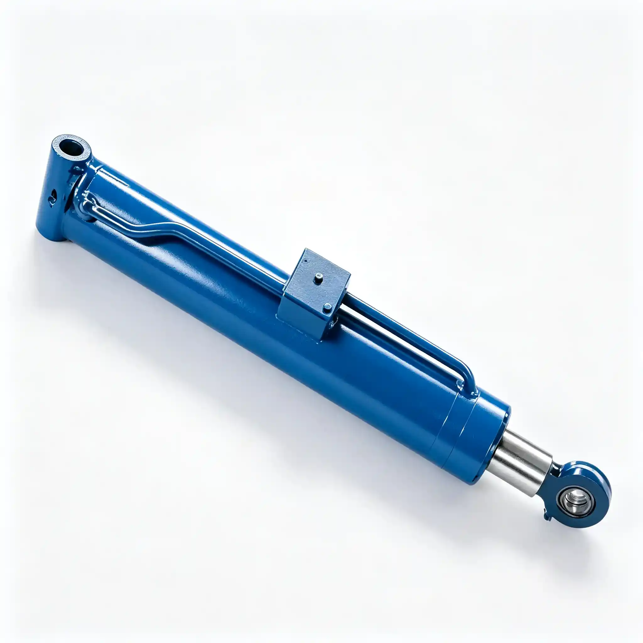
The HCYY11112009 is the main boom extension cylinder — the actuator that pushes the telescopic inner boom section outward along the primary boom axis. At Φ110 mm bore, 23 MPa working pressure, and 100 kg, it is the highest-force and heaviest cylinder in this product line. Its job is mechanically straightforward — extend and retract the telescopic section — but the operating environment makes it one of the most demanding cylinders on the machine.
The extension cylinder lives inside the boom tube, enclosed within the telescopic arm structure. It cannot be visually inspected during normal operation. It carries load along an axis that is rarely truly horizontal — the boom is elevated at working angle, so the cylinder is pushing the inner section uphill against both its own weight and the weight of the platform and payload at the outer end. At full extension with a loaded platform, the cylinder is simultaneously under axial compression and carrying a significant transverse bending load from the unsupported weight of the inner boom section. That is why the Φ75 mm rod is not undersized — it is precisely sized.
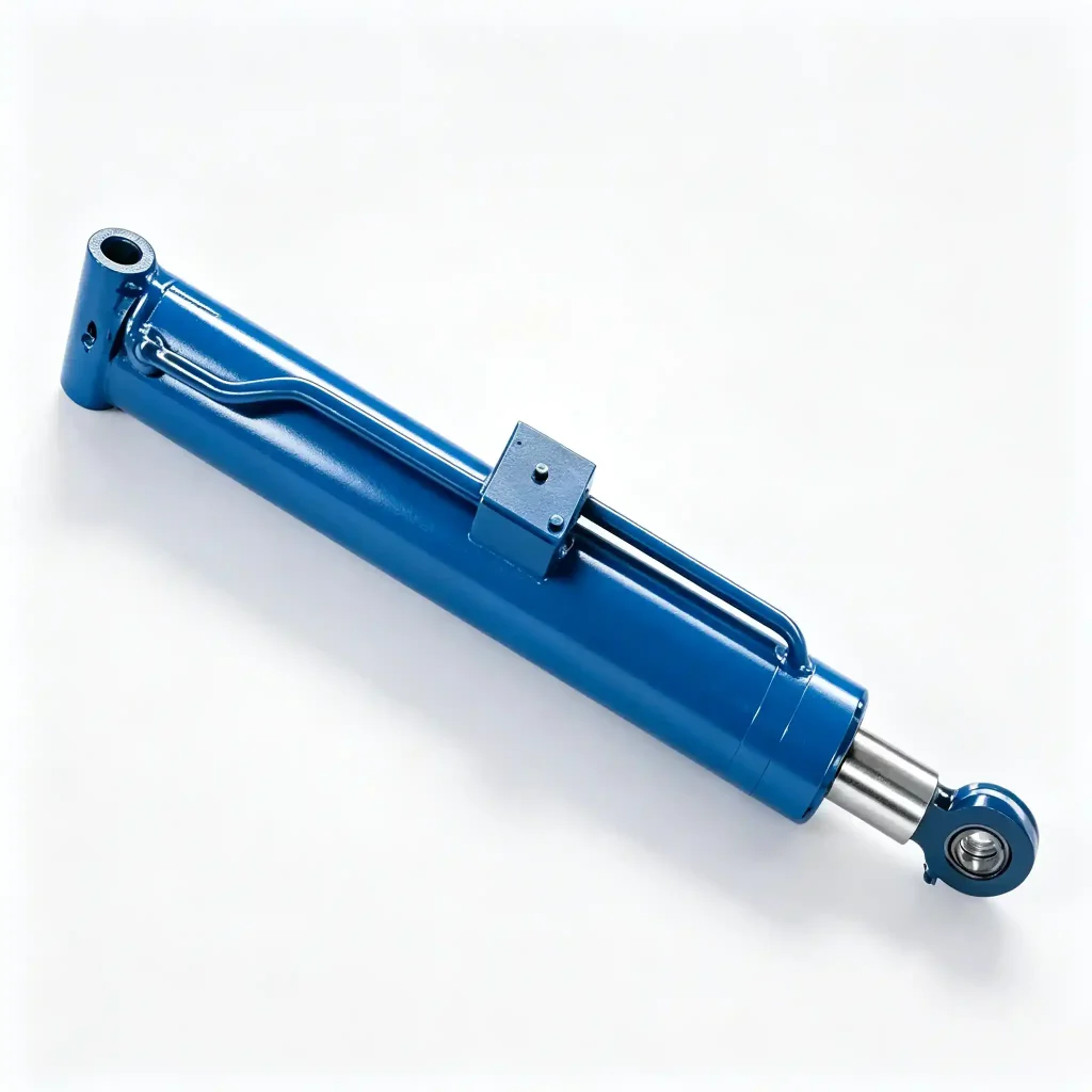
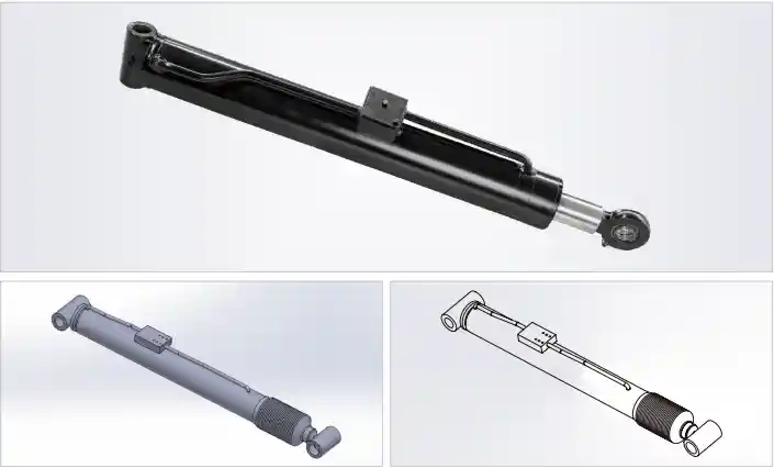
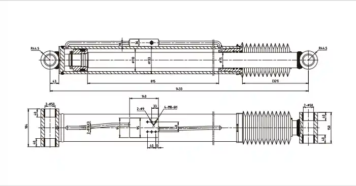
Technical Specifications — Heavy-Duty Boom Extension Cylinder, Φ110 Bore, 23 MPa
| Parameter | Value | What It Means in Practice |
|---|---|---|
| Model | HCYY11112009 | OEM part reference |
| Bore × Rod × Stroke | Φ110 × Φ75 × 815 mm | Largest bore in this range; rod-to-bore ratio 0.68 — balances extension force with retraction speed |
| Working Pressure | 23 MPa | Second-highest in this range; 5 MPa above the main lift cylinders on the same platform |
| Max Withstand Pressure | 34 MPa | 1.48× safety factor — higher margin than most cylinders here, reflecting unpredictable load spikes during extension |
| Stroke | 815 mm | Direct extension travel of inner boom section; determines platform’s additional horizontal reach |
| Installation Distance | 1433 mm | Must fit within the outer boom tube internal length — there is zero clearance tolerance here |
| Weight | 100 kg | Mechanical lifting equipment mandatory — not a two-person lift under any circumstances |
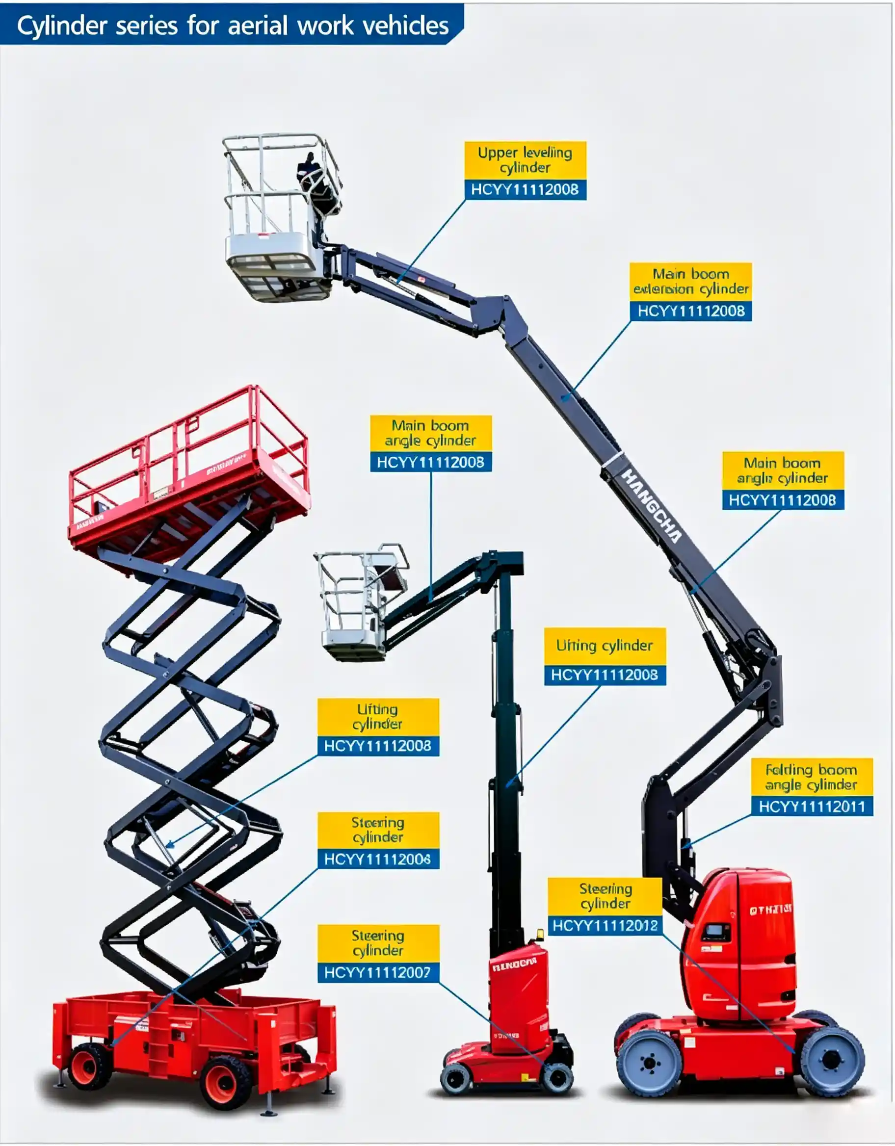
Installation position reference — HCYY11112009 inside the telescopic boom tube
220 kN Extension Force: What the Φ110 Bore at 23 MPa Actually Has to Move
At 23 MPa, the Φ110 mm bore produces an extension force of approximately 219 kN. That figure needs context to be meaningful. The inner telescopic boom section on a mid-size platform (12–18 m working height class) typically weighs 300–600 kg and has a platform plus rated payload of another 200–300 kg hanging at its tip. When the main boom is elevated to a 60° angle and the extension cylinder is pushing the inner section out along the boom axis, the cylinder is working against the component of all those loads acting along the boom axis — plus friction from the slide pads that guide the inner section through the outer tube.
Slide pad friction is often underestimated. New slide pads with correct lubrication add perhaps 3–5% resistance to the axial load. Worn, dry, or contaminated pads can add 15–20% or more — which is one reason why extension cylinder pressures sometimes spike above the nominal working value on older machines that are overdue for slide pad maintenance. The 34 MPa maximum withstand pressure of the HCYY11112009 accommodates these real-world spikes that a clean-machine calculation would not predict.
On retraction, the cylinder uses the rod-side area — bore area minus rod area. With Φ110 bore and Φ75 rod, the annulus area is approximately 5,540 mm² versus the full bore area of 9,503 mm². Retraction force at 23 MPa is therefore roughly 127 kN — adequate to retract the inner section under gravity plus friction, while producing a noticeably faster retraction speed than extension speed for the same pump flow rate. This asymmetry is standard and expected in telescopic boom cylinder design.
Why the HCYY11112009 Carries a 1.48× Pressure Safety Factor — Higher Than Other Cylinders Here
Most cylinders in this range carry a 1.5× safety factor between working pressure and maximum withstand pressure — 18 MPa working / 27 MPa max, or 20 MPa / 30 MPa. The HCYY11112009 at 23 MPa / 34 MPa lands at 1.48×. That is slightly below 1.5× in ratio terms, but the absolute pressure margin is larger: 11 MPa between working and maximum, versus 9–10 MPa on the lifting cylinders.
The reason this margin matters for a boom extension cylinder specifically: the extension circuit is directly connected to the boom’s load-holding valve, and load-holding valves on telescopic booms can experience pressure intensification events during rapid boom movements. If the operator extends the boom quickly and then stops abruptly, the hydraulic momentum in the supply hose can cause a brief pressure spike at the cylinder port that exceeds the pump relief valve setting. The 34 MPa rating means the cylinder barrel, welds, and port fittings survive these events without yielding.
Additionally, the extension cylinder is a structural load-bearing member when the platform is in use at full extension: it is the only thing preventing the inner boom from sliding back into the outer tube under payload weight. A structural failure here — not just a seal failure, but a barrel crack or port failure — would result in immediate uncontrolled boom retraction with the operator in the basket. The higher absolute pressure margin reflects this consequence.
Φ75 mm Rod on a 815 mm Stroke: Buckling Analysis for an Inclined Extension Cylinder
A 815 mm stroke cylinder at moderate bore size would typically use a Φ55–60 mm rod if axial load were the only consideration — the column buckling calculation would support it. The HCYY11112009 uses Φ75 mm because axial load is not the only consideration.
When the boom is elevated and the extension cylinder is pushing the inner section outward, the rod is also carrying a transverse bending load. The inner boom section’s weight acts downward through the rod at the point where the inner boom connects to the cylinder rod end — and because the rod is horizontal inside an elevated boom, this weight creates a bending moment at the rod. The magnitude depends on boom angle, inner section weight, and how far along the inner section the attachment point is.
At Φ75 mm, the rod’s section modulus is approximately 2.6× higher than a Φ55 mm rod — meaning it bends far less under the same transverse load. Less rod deflection means the rod guide bushing at the cylinder head carries lower side load, which extends guide bushing life. It also means the rod seal experiences more uniform contact pressure around its circumference, which is directly correlated with longer seal service life in inclined-installation cylinders.
Installation Inside the Boom Tube: Dimensional Constraints and Replacement Procedure
The 1433 mm installation distance is constrained on both ends by the boom tube geometry. The cylinder tail (barrel end) is pinned to the outer boom section, and the rod end is pinned to the inner boom section. These pin locations are fixed by the boom structure — the cylinder’s retracted length must fit exactly between them when the inner section is fully retracted, and the cylinder’s extended length (1433 + 815 = 2248 mm) must reach the inner section’s extended pin position without binding.
A replacement cylinder that is 20 mm longer in installation distance will prevent the inner section from fully retracting — it will bottom out on the cylinder before reaching the travel stop, potentially damaging the boom structure. A cylinder 20 mm shorter will leave a gap at full retraction that the hydraulic lock cannot bridge, causing the inner section to float slightly — which operators notice as “play” in the boom tip at full retraction.
Replacement procedure requires the main boom to be fully lowered and the inner section manually supported before the cylinder can be removed — with the boom elevated, removing the extension cylinder drops the inner section and platform. On a 100 kg cylinder, this operation requires a crane or hydraulic lift with rated capacity, proper rigging points, and a two-person minimum team. Attempting to replace this cylinder without mechanical lifting support is a serious handling risk.
Hydraulic System Sizing: Flow Demand of a Φ110 Bore Extension Cylinder
The Φ110 bore has a piston area of approximately 9,503 mm². At a typical extension speed of 0.08 m/s (80 mm per second — a moderate telescoping speed for operator comfort), the cylinder demands approximately 45.6 L/min of hydraulic flow. At 0.1 m/s, the demand rises to 57 L/min.
This flow demand has practical implications for system designers and troubleshooters. If the machine’s pump maximum output is 50 L/min and the operator selects maximum extension speed, the pump will be at full capacity — any simultaneous function demand (boom elevation, leveling correction) will cause a measurable extension speed reduction. Operators on high-hour machines sometimes report “slow extension” that is actually a pump wear issue driving reduced flow delivery, not a cylinder problem.
For maintenance teams troubleshooting slow extension: before condemning the cylinder, verify pump flow output under load. A cylinder that passes a 34 MPa proof test and shows zero external leakage cannot produce slow extension by itself — slow extension at correct pressure is always a flow supply issue upstream of the cylinder.
Hydraulic Fluid Cleanliness Requirements for Long Extension Cylinder Life
The HCYY11112009’s piston seal and rod seal operate at 23 MPa against a precision-honed Φ110 mm bore and a hard-chrome Φ75 mm rod surface. At this bore size, contamination particles that would pass through a smaller cylinder’s clearances are large enough to score the bore surface or embed in the seal lips — causing accelerated leakage that starts gradually and worsens rapidly.
The hydraulic system serving this cylinder should maintain fluid cleanliness at ISO 4406 class 16/14/11 or better, with a return-line filter rated at 10 µm absolute (Beta₁₀ ≥ 200). If the machine operates in dusty environments — construction sites, quarries, demolition work — increase filter change frequency and inspect the cylinder rod wiper seal condition at each major service interval. A wiper seal that is cracked, torn, or missing brings contamination directly onto the chrome rod surface on every retraction stroke.
Platform Types and Applications for the HCYY11112009 Extension Cylinder
- Single-stage telescopic boom lifts (12–20 m working height) — the HCYY11112009 is the sole extension cylinder on platforms where one telescoping stage provides all the horizontal reach. The full 815 mm stroke corresponds to the complete extension range of the inner boom section.
- Two-stage telescopic boom lifts — used as the primary (outer) extension cylinder on larger platforms where a second inner stage provides additional reach. In this configuration, the HCYY11112009 handles the higher-load outer stage extension while a smaller cylinder manages the lightly-loaded inner stage.
- Combination articulating-telescopic boom lifts — where a telescopic upper section extends horizontally after the knuckle boom has positioned the upper arm. The extension cylinder in this configuration sees particularly variable load angles as the knuckle position changes.
- Heavy-capacity platforms (rated ≥ 230 kg platform load) — where the extension cylinder load analysis requires the Φ110 bore output to maintain rated capacity at maximum horizontal reach without reaching the relief valve setting during normal operation.
- OEM production supply and refurbishment — aerial platform manufacturers requiring a certified production-ready extension cylinder, and refurbishment workshops replacing high-hour or damaged extension cylinders as part of structural life-extension programs.
Request HCYY11112009 Technical Package and RFQ
At 100 kg and 23 MPa, sourcing the HCYY11112009 requires more than a price list — you need dimensional drawings, pressure test certification, material traceability, and confirmed lead times before committing to a replacement or production order. We provide all of this as standard with every inquiry.
- 34 MPa hydrostatic proof test certificate per unit
- Full dimensional drawing with port locations and pin bore detail
- Material mill certificates for barrel, rod, and structural components
- Export crating rated for international air or sea freight
- OEM annual supply agreements with committed lead time
Send your RFQ with platform model and boom specification — include whether you need a one-off replacement or production volume. We respond within one business day.