Descrição
HCYY11112010 — Main Boom Lift Hydraulic Cylinder | Φ70×Φ40×555, 20 MPa
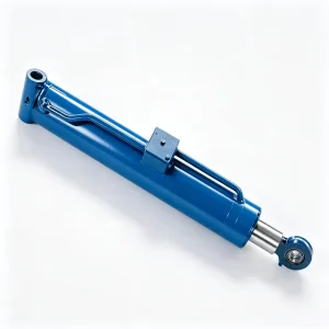
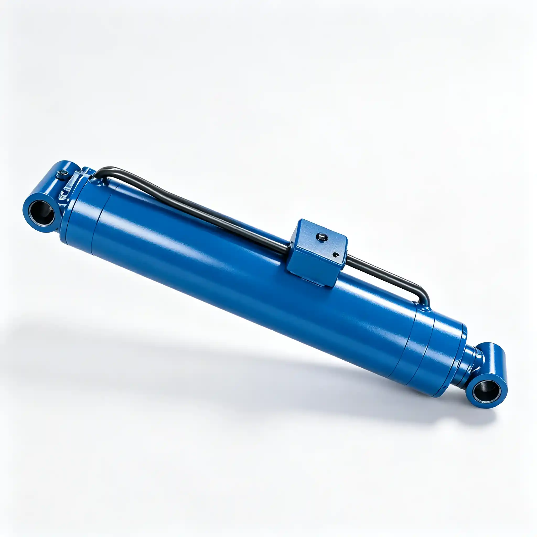
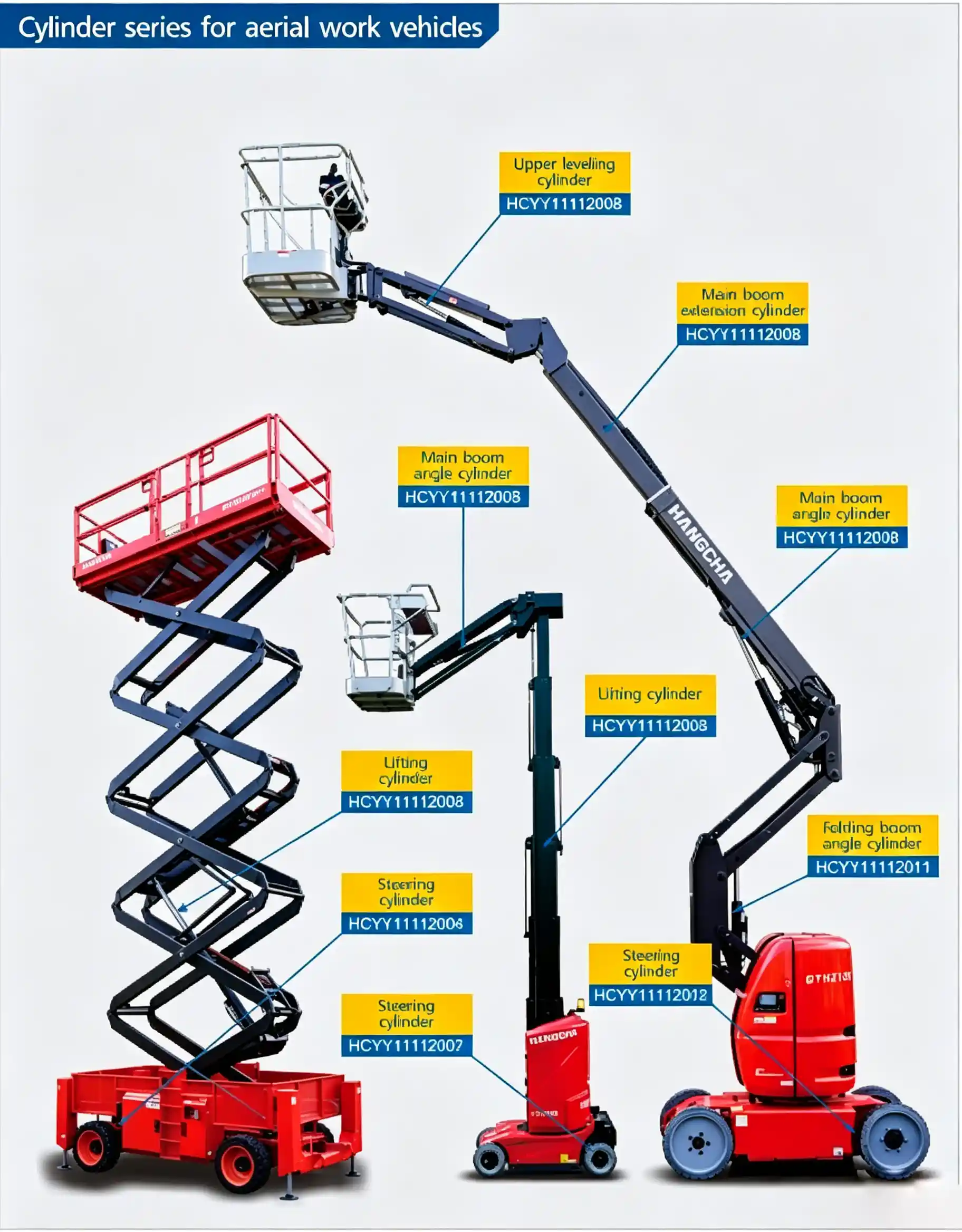
The HCYY11112010 is the main boom angle cylinder — the actuator that raises and lowers the primary boom arm of a telescopic or articulating aerial work platform. With a Φ70 mm bore, 555 mm stroke, and 20 MPa working pressure, it drives the boom through its full elevation arc from the transport-horizontal position to maximum working angle. At 28 kg, it is manageable for a two-person maintenance team, but its engineering demands are anything but ordinary.
The main boom angle cylinder has a duty that is often misunderstood: its most mechanically demanding state is not the moment of lifting — it is the hours spent holding the boom stationary at working height. While the operator works at elevation, the cylinder sits under continuous compressive load from the weight of the entire boom assembly plus the platform and payload. Any internal seal bypass in this condition causes the boom to slowly descend — a drift that accumulates invisibly until the platform has moved far enough for the operator to notice. This is why the load-holding performance of the HCYY11112010 is tested and verified to a stricter standard than the extension or steering cylinders on the same machine.
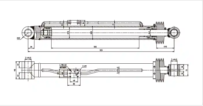
Technical Specifications — Main Boom Angle Cylinder, Φ70 Bore, 20 MPa, 555 mm Stroke
| Parameter | Value | What It Means in Practice |
|---|---|---|
| Model | HCYY11112010 | OEM part reference |
| Bore × Rod × Stroke | Φ70 × Φ40 × 555 mm | Rod-to-bore ratio 0.57 — thinner rod than the leveling cylinder, appropriate for predominantly axial loading at this position |
| Working Pressure | 20 MPa | Extension force ≈ 76.9 kN at bore area of 3,848 mm² |
| Max Withstand Pressure | 30 MPa | Exactly 1.5× working pressure — standard safety factor for structural load-holding cylinders |
| Stroke | 555 mm | Covers full boom arc from transport angle to maximum working elevation — typically 0° to 75–80° |
| Installation Distance | 923 mm | Pin-to-pin retracted length; sets the boom’s starting angle at full retraction — geometry-critical |
| Weight | 28 kg | Two-person manual handling is feasible with correct technique; mechanical assist recommended for confined-space installation |
Lifting Is Easy. Holding Is the Hard Part: Load Analysis at Working Height
When the main boom is elevated to 75° and the operator is working, the cylinder is stationary — but it is far from unloaded. The force it must sustain depends on the moment arm geometry at that angle. At high boom elevations, the cylinder’s mechanical advantage improves (the perpendicular distance from the boom pivot to the cylinder line of action increases), which means the cylinder force required to hold the boom decreases compared to the force needed to lift it from a low angle.
The critical point is the low-angle lift position — when the boom is near horizontal and the cylinder’s mechanical advantage is worst. This is where the 76.9 kN extension force is most heavily demanded. A platform rated for 250 kg payload with a boom assembly weighing 800 kg requires the cylinder to generate substantial moment at a short lever arm as it initiates the lift from near-horizontal. The 20 MPa system pressure and Φ70 bore are sized for this worst-case condition, with the system relief valve preventing the cylinder from being overloaded if the rated payload is exceeded.
At high angles, the holding load drops — but the consequence of a seal bypass event becomes more severe. A boom at 75° that slowly descends due to cylinder bypass brings the platform tip through a large arc for a small angle change. A 2° descent at 75° elevation moves the platform tip several hundred millimeters downward and inward simultaneously, which is not a subtle movement for an operator working against a fixed structure above them.
Boom Drift: How Internal Bypass in the Main Angle Cylinder Manifests and How Fast It Progresses
Internal bypass in a main boom angle cylinder follows a consistent pattern. Early-stage wear produces a slow drift — perhaps 10–20 mm of boom retraction over 15–20 minutes at static hold under full rated load. An operator working a 30-minute task at height may not notice this. A supervisor doing a static drift test with a reference mark on the cylinder rod will catch it.
As the piston seal continues to degrade, bypass rate increases. The drift becomes noticeable to operators within 5–10 minutes of static hold. At this stage, the machine should be taken out of service — not because the seal is about to fail catastrophically, but because the platform can no longer maintain the ±2° positional tolerance required under EN 280 and ANSI A92 during extended static use.
What accelerates piston seal degradation in main boom angle cylinders specifically:
- Contaminated hydraulic fluid — particles above 10 µm embed in the piston seal lips and score the bore surface. Once the bore is scored, seal replacement alone will not stop bypass — the bore damage creates a bypass path that no seal can bridge.
- Thermal cycling in outdoor operation — a machine left overnight at 0°C and operated immediately in full sun at 35°C cycles the hydraulic fluid viscosity across a wide range. Cold starts with high-viscosity fluid generate brief pressure spikes above the working pressure that stress the piston seal on every morning startup.
- Operating at elevated system pressure — some operators or technicians raise the system relief valve setting above the design value to compensate for a weak pump or restricted flow. This increases the differential pressure across the piston seal beyond its design point and accelerates wear nonlinearly.
- Long static holds under full load — construction and maintenance platforms that hold position for hours at a time accumulate seal creep damage faster than machines that cycle frequently. Seal materials under sustained compression at 20 MPa experience slow plastic deformation that reduces their contact force against the bore wall over time.
The 923 mm Installation Distance: Why It Sets the Boom’s Transport Configuration
The 923 mm pin-to-pin retracted length is not just a mounting dimension — it is the dimension that determines where the boom sits when the cylinder is fully retracted. On a telescopic boom lift, the transport position is the boom fully retracted and lowered to its minimum angle, resting on the transport cradle or within the travel lock. The boom angle at this fully-retracted-cylinder position is fixed by the 923 mm installation distance and the geometric positions of the two pin joints on the boom structure.
If a replacement cylinder has an installation distance of 933 mm — just 10 mm longer — the boom cannot fully retract to its transport position. It will sit 10 mm “open” in the cylinder, which translates to a small but measurable positive boom angle. On most platforms, this is enough to prevent the travel lock from engaging, which triggers the boom-not-stowed interlock and prevents the machine from driving. The operator sees a drive lockout with no obvious cause, because the boom visually appears to be down.
Conversely, a cylinder 10 mm shorter in installation distance than the original allows the boom to over-retract slightly — the boom drops below its intended transport angle and may contact the chassis or counterweight structure, causing damage that is not immediately visible but can crack boom tube welds over repeated travel cycles.
Φ40 Rod on 555 mm Stroke: Column Stability Verification for Main Boom Angle Cylinders
A Φ40 mm rod at 555 mm stroke with a pin-pin end condition gives a slenderness ratio that places the cylinder safely within the elastic buckling range under the maximum compressive load it will see at 20 MPa. The critical buckling load for a Φ40 mm rod at this effective length — using the Euler formula with a safety factor of 3.5 applied — remains above the maximum axial force the system pressure can generate on the rod side of the piston.
The pin-to-pin mounting of a boom angle cylinder is important here: the pin joints at both ends of the cylinder allow angular movement, which means the effective end condition is a pin-pin column — not fixed-fixed. The pin-pin effective length equals the actual installation length, which is the most conservative (weakest) column assumption. The Φ40 mm rod passes the buckling check at 923 mm effective length with the required safety margin, which is why a thicker rod is not necessary at this position unlike the extension cylinder that mounts in an inclined, bending-loaded configuration.
The thinner rod also has a practical benefit: the annulus area on the retraction side is larger than it would be with a thicker rod, producing a higher retraction force — useful for pulling the boom back down against gravity when it has been elevated beyond 45° and gravity alone is insufficient to ensure controlled lowering at the required speed.
HCYY11112010 vs HCYY11112005: Two Main Boom Angle Cylinders, Different Engineering Priorities
Both the HCYY11112010 and the HCYY11112005 carry the designation “main boom angle cylinder,” but they serve different platform geometries and reflect different design choices:
| Parameter | HCYY11112010 | HCYY11112005 |
|---|---|---|
| Bore × Rod | Φ70 × Φ40 | Φ55 × Φ50 |
| Rod-to-bore ratio | 0.57 — standard for axial-dominant loading | 0.91 — thick rod for extreme buckling resistance |
| Extension force at rated pressure | ≈ 76.9 kN at 20 MPa | ≈ 49.9 kN at 21 MPa |
| Stroke | 555 mm | 506 mm |
| Installation distance | 923 mm | 1259.7 mm |
| Design priority | Higher force output, balanced rod-annulus area | Extreme column stability, retraction force symmetry |
The HCYY11112005’s near-equal bore and rod diameter (Φ55 bore / Φ50 rod) tells you its designer was primarily concerned with buckling: the thick rod resists column failure in a long installation configuration, and the tiny annulus area on the retraction side means retraction force and extension force are nearly equal — which simplifies the control valve sizing. The HCYY11112010’s Φ70 bore with Φ40 rod prioritizes raw extension force output, accepts a more conventional rod size, and relies on its shorter installation distance (923 mm vs 1259.7 mm) for column stability. Do not substitute one for the other — the installation distances are completely different and they will not interchange even on platforms that use the same working pressure circuit.
Platform Types This Cylinder Is Designed For
- Single-boom telescopic aerial work platforms — where the HCYY11112010 is the sole elevation cylinder, controlling the full angular travel of the main boom from transport to maximum working height. The 555 mm stroke accommodates boom designs with a pivot-to-cylinder attachment distance that produces the required angular range at this stroke.
- Articulating boom lifts — lower boom elevation — on two-section knuckle boom platforms, the lower boom angle cylinder controls the primary elevation arc while the upper section (folding boom) is separately actuated. The HCYY11112010’s force output and stroke fit the lower boom geometry of mid-size articulating platforms.
- Construction and infrastructure platforms — machines working on building sites, bridges, and large-structure maintenance where the boom holds at maximum elevation for extended periods, making the cylinder’s static load-holding performance the dominant service requirement.
- Rental fleet machines with high static-hold cycles — painting contractors, glazing installers, and facade maintenance operations where the platform holds position for 20–60 minutes at a time between repositioning moves — a duty cycle that puts sustained stress on the piston seal.
- OEM and aftermarket replacement — platforms where the original main boom angle cylinder matches the 923 mm installation distance, 555 mm stroke, and Φ70 bore specification of the HCYY11112010.
Request HCYY11112010 — Static Load-Hold Test Data Included
We supply the HCYY11112010 to boom lift manufacturers, authorized service centers, and fleet operators. Every unit is tested at 30 MPa hydrostatic proof pressure and undergoes a static internal leakage test under working pressure before dispatch. The test report is included with each shipment — not available on request, included as standard.
- 30 MPa hydrostatic proof test certificate per unit
- Static internal leakage test result (load-hold verification)
- Dimensional drawing with 923 mm installation distance confirmed
- Material certificates for rod and barrel on request
- OEM supply agreements with annual volume and lead time commitment
Send your RFQ with platform model and boom specification — one business day response with technical confirmation and commercial pricing.