
Hollow Shaft Right Angle Planetary Gearbox: When Should You Use One?
Most engineers reach for a keyed shaft output by default. It’s familiar, it connects to standard couplings, and it works for the majority of applications. But there’s a category of drive installation where the hollow shaft configuration is clearly the better answer—and where defaulting to a keyed shaft creates unnecessary complexity, added assembly length, additional backlash sources, and an alignment problem that didn’t need to exist.
Understanding when a hollow shaft right angle planetary gearbox is the right tool—and when it isn’t—comes down to one core question: is the gearbox connecting to a shaft, or is it connecting to a component that was designed to receive a shaft? If the gearbox is connecting to a shaft, hollow shaft output deserves serious consideration.
What a Hollow Shaft Gearbox Actually Does
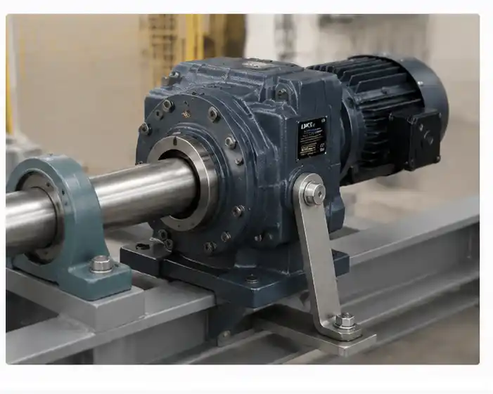
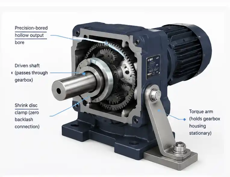
In a hollow shaft right angle planetary gearbox, the output section has a precision-bored through-hole instead of a protruding shaft. The driven shaft—a conveyor shaft, a roll shaft, a spindle, any shaft whose diameter matches the bore—slides through this hole and is clamped inside it. The gearbox drives the shaft directly, and the shaft drives whatever it’s connected to on the far end.
The connection between the gearbox bore and the driven shaft can be made in two ways. A keyway and key in the bore provides a positive mechanical drive—simple, proven, and capable of transmitting high torque, but it introduces a small amount of torsional play from keyway clearance. A shrink disc (also called a locking ring or interference fit clamp) clamps the gearbox bore tightly around the shaft using friction—essentially zero backlash at the output interface, high torque capacity, and easy removal without shaft damage when service is required.
The gearbox housing, meanwhile, is held stationary by a torque arm connected to the machine frame. The shaft rotates inside the bore; the housing doesn’t rotate. This is the fundamental operating principle—and also the fundamental installation requirement that hollow shaft configurations impose.
The Applications Where Hollow Shaft Makes the Most Sense
Conveyor head and tail shaft drives. This is the classic hollow shaft application. The conveyor’s drive shaft—typically a solid steel shaft supported by pillow block bearings at each end—runs through the gearbox output bore. The gearbox motor hangs off the side of the conveyor frame, the housing torque arm fastens to the frame, and the output bore clamps directly to the shaft. No coupling, no shaft stub on the gearbox side, no alignment procedure beyond seating the bore on the shaft. Installers familiar with this arrangement prefer it to keyed shaft setups precisely because it’s faster, tighter, and more compact.
Roll and drum drives. Paper mills, film processing lines, textile machinery, and metal rolling operations drive rotating rolls or drums directly. The roll shaft extends beyond the roll body and into the gearbox bore. The gearbox mounts alongside the machine frame with a torque arm. Again: no coupling, no intermediate shaft, no alignment issues.
Fan and blower shaft drives. Hollow shaft gearboxes are used on fan shaft drives where the motor and gearbox assembly mounts directly on the fan shaft. The shaft passes through the gearbox and into the fan hub. The assembly is compact, the shaft loading is clean, and the installation is substantially simpler than a shaft-output gearbox with a coupling and separate shaft extension.
Agitator and mixer drives. Vertical hollow shaft gearboxes drive agitator shafts in tanks and vessels. The agitator shaft passes through the gearbox from below; the motor sits on top. This arrangement eliminates the long shaft stub and coupling that a conventional shaft-output gearbox would require, and keeps the overall drive assembly height lower.
Compact servo axis drives. In servo-driven machinery where the gearbox output connects directly to a precision spindle or a rotary axis shaft, a hollow shaft with a shrink disc provides a backlash-free, compact connection that no keyed shaft plus coupling arrangement matches.
The Advantages—Stated Honestly
The case for hollow shaft output rests on four genuine advantages, not marketing claims.
Shorter total assembly length. Eliminating the output coupling and its associated hub lengths, spacer, and shaft stub saves real space. For a typical industrial setup, the difference can be 80–200 mm in the output axis direction. In constrained machine frames, that’s significant.
Fewer backlash sources. Every mechanical joint between the gearbox output and the driven load is a potential backlash source. A keyed shaft plus jaw coupling plus hub adds keyway clearance, coupling spider compliance, and hub bore clearance to the gearbox’s internal backlash. A hollow shaft with shrink disc eliminates all three. Total system backlash is lower—sometimes significantly lower—without any change to the gearbox’s internal gear geometry.
No alignment procedure. Mounting a keyed shaft gearbox to a driven component requires shaft alignment—measuring and correcting angular and parallel misalignment between the gearbox output shaft and the driven shaft. Done poorly, misalignment generates bearing side loads that shorten gearbox and coupling life. A hollow shaft gearbox mounted on the driven shaft is self-aligning: the bore fits the shaft, concentricity is inherent in the fit, and there’s no independent alignment step.
Cleaner load path. In a hollow shaft arrangement, the driven shaft is supported by the gearbox output bearing in addition to its own external bearings. The shaft runs through the gearbox output section with support along the bore length, rather than being cantilevered from the gearbox shaft end. For moment load handling, this is a more favorable geometry than a short shaft stub with a coupling at the end.
The Requirements You Need to Satisfy
Hollow shaft gearboxes impose three requirements that keyed shaft units don’t. These are manageable—but they must be planned for before specifying the hollow shaft configuration.
The driven shaft diameter must match the bore. Available bore diameters are fixed by the gearbox model and frame size—you can’t order a custom bore diameter in a standard catalog item. Confirm the available bore sizes for the specific gearbox model before specifying hollow shaft. If the driven shaft diameter doesn’t match any available bore, a keyed shaft with a coupling is the practical solution.
A torque arm or anti-rotation bracket is required. The gearbox housing must be prevented from rotating with the driven shaft. The torque arm connects the housing to a fixed point on the machine frame. It must be designed for the full output torque of the gearbox with an appropriate safety factor—underdesigning the torque arm is a failure mode that can be difficult to diagnose because the rotation is gradual and may not immediately cause an obvious failure. The arm should allow free axial movement between the gearbox housing and the frame (to accommodate thermal expansion and shaft deflection) while restraining rotation—a slotted hole or spherical joint at one connection point is typical.
Shaft removal requires gearbox removal or disassembly. In a keyed shaft arrangement, the driven component can often be removed from the gearbox shaft without disturbing the gearbox installation. In a hollow shaft arrangement, the driven shaft runs through the gearbox—removing the shaft may require removing or at least loosening the gearbox. In applications where the driven shaft is frequently replaced or serviced, this additional disassembly step is worth factoring into the maintenance plan.
Keyway vs. Shrink Disc: Which Clamping Method to Use
The choice between keyway and shrink disc in the hollow bore affects backlash, installation, and service requirements.
A keyway is simple, inexpensive, and familiar. It transmits torque reliably and is easy to assemble and disassemble. The limitation is keyway clearance—the key has a small amount of play in the keyway, which contributes a small angular play at the output interface. For most industrial conveyor and material handling applications, this play is acceptable. For precision servo applications where total system backlash must be minimized, it’s a consideration.
A shrink disc clamps the bore around the shaft using a set of tapered rings that are tightened by a series of bolts. The clamping force creates friction that transmits torque without any mechanical play—effective backlash at the output interface is essentially zero. Installation requires tightening the shrink disc bolts in sequence to a specified torque, and removal requires releasing the bolts and breaking the interference fit with a puller tool. The process is more involved than sliding on a keyed coupling hub, but the result is a tighter, stiffer output connection that works particularly well in servo applications.
For high-precision servo applications: specify shrink disc. For general industrial drives where keyway clearance is acceptable: either works, and keyway is simpler.
When Not to Use a Hollow Shaft
Hollow shaft is not the universal improvement over keyed shaft that some applications treat it as. It’s the wrong choice when:
- The driven component is not a shaft—it’s a coupling, a sprocket, a pulley, or any component that receives a shaft rather than being one. These connect naturally to a keyed shaft output; adapting them to a hollow shaft bore requires machining a stub shaft that defeats the hollow shaft’s advantages.
- No suitable torque arm mounting point exists on the machine frame. A hollow shaft gearbox without a properly designed torque arm is a safety and reliability problem. If the machine frame doesn’t offer a practical attachment point for the torque arm, design the machine to accommodate a keyed shaft arrangement instead.
- The driven shaft diameter doesn’t match any available bore size in the product line. A custom bore requires custom manufacturing lead time and cost that may not be justified.
- The driven shaft requires frequent removal for service or inspection. In applications where the shaft comes out regularly, the additional disassembly step imposed by a hollow shaft arrangement adds maintenance time compared to a keyed shaft with a coupling.
Sizing Considerations Specific to Hollow Shaft Designs
The selection parameters—torque, ratio, backlash, radial load—are the same for hollow shaft units as for keyed shaft units. A few points are specific to the hollow shaft configuration:
Bore wall thickness affects maximum torque. A larger bore diameter in a given frame size means less wall thickness in the output section and potentially lower torsional stiffness. At the limits of the bore range for a given frame, verify the torque rating isn’t reduced at the larger bore diameter—some manufacturers publish bore-specific torque de-rating factors.
Shaft fit tolerance matters. The fit between the driven shaft and the gearbox bore is specified in the product documentation. For keyway connections, a standard H7/k6 or H7/n6 fit is typical. For shrink disc connections, the shaft surface finish and dimensional tolerance requirements are specified by the shrink disc manufacturer. Following these specifications is important—an undersized shaft in an oversized bore won’t transmit the rated torque reliably regardless of how tight the shrink disc is clamped.
Radial load from the driven shaft’s weight or loading. In vertical installations where the gearbox is mounted at the top and the driven shaft hangs below, the weight of the shaft and driven component applies a constant radial load to the gearbox output bore. Calculate this load and confirm it’s within the gearbox’s rated radial load for the hollow shaft configuration.
Frequently Asked Questions
Can any right angle planetary gearbox be ordered in hollow shaft configuration?
Not necessarily—hollow shaft availability depends on the specific product line and frame size. Some manufacturers offer hollow shaft as a standard option across their range; others offer it only in selected frame sizes or as a custom configuration. Confirm hollow shaft availability for the specific model and frame size before designing it into the machine.
How do I specify the bore diameter when ordering a hollow shaft gearbox?
Specify the driven shaft diameter directly. The manufacturer will confirm which bore size is available for that shaft diameter in the selected frame size. For keyway connections, also specify the keyway dimensions. For shrink disc connections, specify the shaft outer diameter and surface finish requirement—the manufacturer or shrink disc supplier will provide the corresponding specifications.
What is the maximum shaft diameter that can pass through a hollow shaft gearbox?
Maximum bore diameter is frame-size-specific and varies by manufacturer. As a general orientation, small servo-grade frames (40–70 mm output flange) typically offer bores up to 20–30 mm. Medium frames (90–120 mm) typically offer up to 40–60 mm. Large industrial frames can offer 80 mm or more. Confirm with the manufacturer’s product data for the specific unit.
Is a hollow shaft gearbox harder to install than a keyed shaft unit?
The bore-on-shaft fitting is generally straightforward—slide the gearbox onto the shaft, align the keyway or position the shrink disc, tighten to specification. The additional step is designing and installing the torque arm, which requires identifying a suitable attachment point on the machine frame and fabricating a bracket. For engineers familiar with the configuration, this is routine. For those doing it for the first time, the torque arm design and attachment point selection benefit from careful thought before commissioning.
Does a hollow shaft gearbox need a special coupling?
No coupling is needed between the gearbox and the driven shaft—that’s the point of the hollow shaft configuration. However, the motor still connects to the gearbox input through the standard servo motor adapter flange and clamp coupling, same as any other configuration. The “no coupling” benefit applies to the output side only.
What happens if the torque arm fails or is too short?
Without a functioning torque arm, the gearbox housing will rotate slowly with the driven shaft under load. In mild cases this causes cable strain and connector damage as the motor cable winds around the assembly. In severe cases the housing rotation can cause structural contact with adjacent components or jam the motor cable, leading to motor or gearbox failure. The torque arm is a safety-critical element of the hollow shaft installation—it must be correctly designed, properly fastened, and periodically inspected.
Is a Hollow Shaft Right Angle Planetary Gearbox Right for Your Application?
If your machine drives a shaft directly—a conveyor shaft, a roll, a spindle, an agitator—a hollow shaft right angle planetary gearbox is worth specifying over a keyed shaft unit. The installation is simpler, the backlash is lower, and the assembly is more compact. The additional requirement is a properly designed torque arm—a manageable engineering task that pays dividends in a cleaner, more reliable drive installation.
EPG Canada Sales Representative Co., Ltd provides gearbox selection and application support for Canadian OEMs and industrial equipment manufacturers across North America. If you’re evaluating hollow shaft versus keyed shaft output for a specific drive application, send the details and we can help confirm the right configuration.
Email: [email protected]
Phone: +1-604 719 2870
Address: 10891 Hogarth Dr, Richmond, BC V7E 3Z9, Canada
For hollow shaft enquiries, include: driven shaft diameter and length through the gearbox; required output torque and gear ratio; torque arm mounting options on the machine frame; keyway or shrink disc preference; backlash requirement; and duty cycle. See the full planetary gearbox range, the right angle planetary gearbox series, or contact us directly.