描述
The Anti-Tip Cylinder: Why the Most Important Safety Component on a Crawler Crane Rarely Gets Talked About
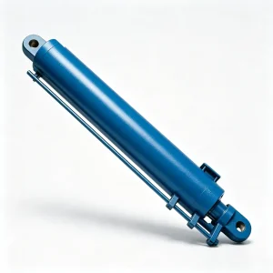
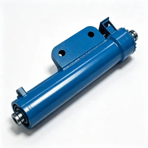
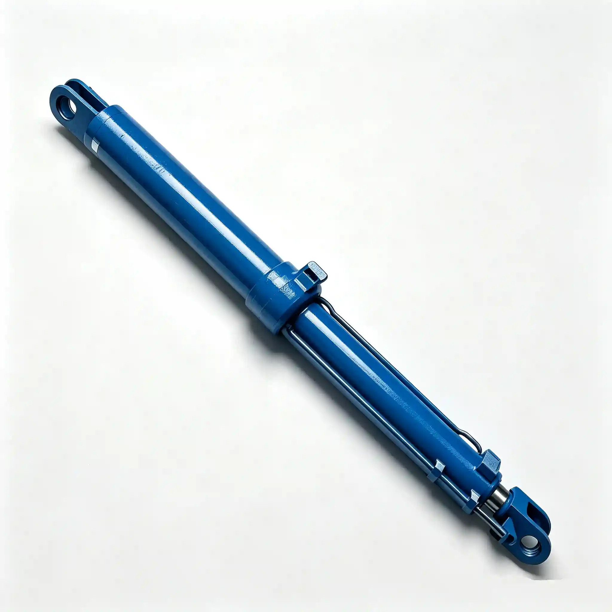
The crawler crane boom anti-tip hydraulic cylinder (HCYY11112019) doesn’t lift anything. It doesn’t lower anything. Its entire purpose is to prevent the boom from tipping sideways — the one failure mode in crane operation that offers essentially zero recovery time once it begins. When a lattice boom starts moving laterally out of the crane’s lifting plane, the anti-tip cylinder is the last active mechanical element standing between a controlled lift and a catastrophic structural collapse.
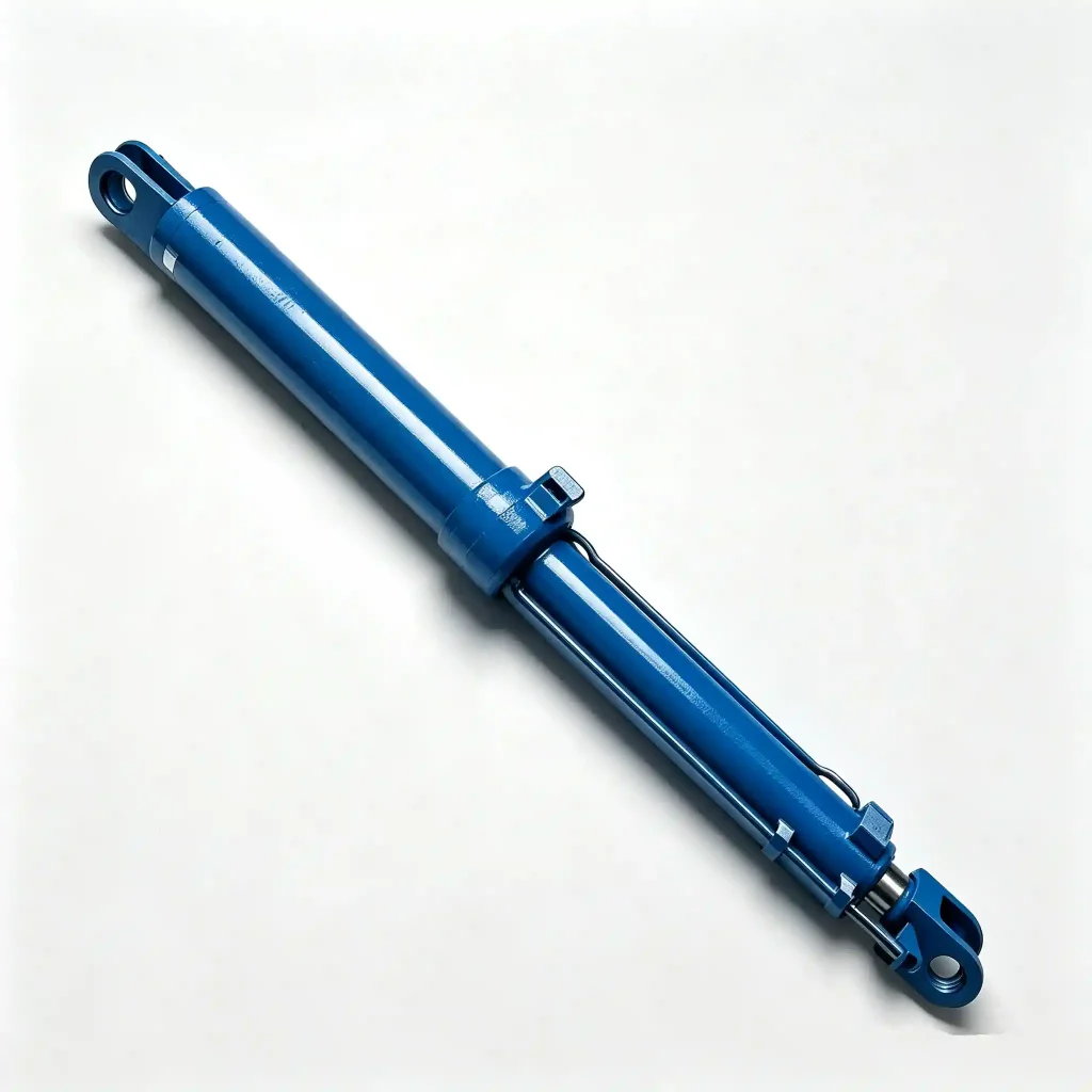
Lateral boom instability on a crawler crane can be triggered by several real-world events: an off-center load that develops a swing, a side pull during rigging, wind loading on a large surface-area boom, or a crane traveling on a cross-slope with a suspended load. In all of these cases, the boom stabilizer cylinder is the active structural member that resists lateral displacement at the boom’s mid-section — preventing the kind of progressive tipping that no amount of operator reaction time can stop once it passes a critical threshold.
At Φ190 mm bore and 820 kg, the HCYY11112019 is the second-heaviest cylinder in the crawler crane hydraulic circuit. Its unusually long installation distance of 4300 mm relative to its 1400 mm stroke reflects the geometry of its mounting position — spanning a wide lateral brace point on the boom structure to maximize the moment arm available for resisting lateral tipping forces.
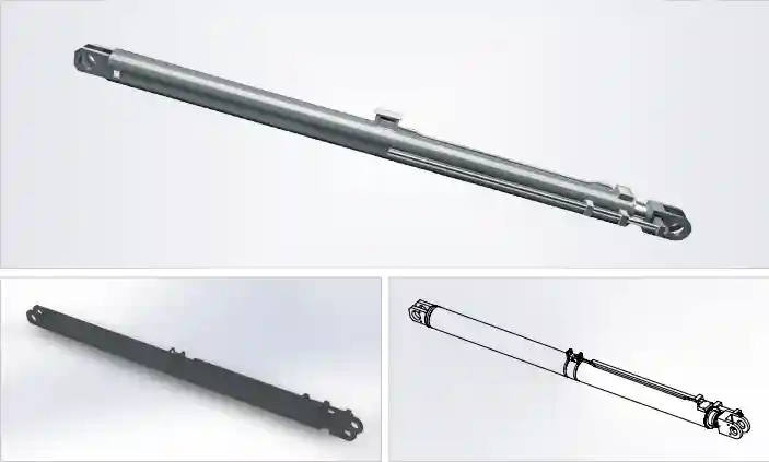
Technical Specifications — HCYY11112019 Boom Anti-Tip Hydraulic Cylinder
| Parameter | Value | Engineering Context |
|---|---|---|
| Model | HCYY11112019 | Crawler crane boom anti-tip / lateral stabilizer series |
| Bore × Rod × Stroke | Φ190 × Φ160 × 1400 mm | Near equal bore-to-rod ratio: bidirectional force capacity for both push and pull lateral loading |
| Working Pressure | 31.5 MPa | Push force ≈ 894 kN; pull force ≈ 633 kN at rated pressure |
| Max Withstand Pressure | 40 MPa | 27% overpressure safety margin; impact-load rated |
| Stroke (Trip) | 1400 mm | Accommodates full lateral adjustment range of boom brace geometry |
| Installation Distance | 4300 mm | Wide lateral span maximizes anti-tip moment arm; the largest installation distance of the three crane cylinders |
| Weight | 820 kg | Second-heaviest cylinder in the crawler crane system |
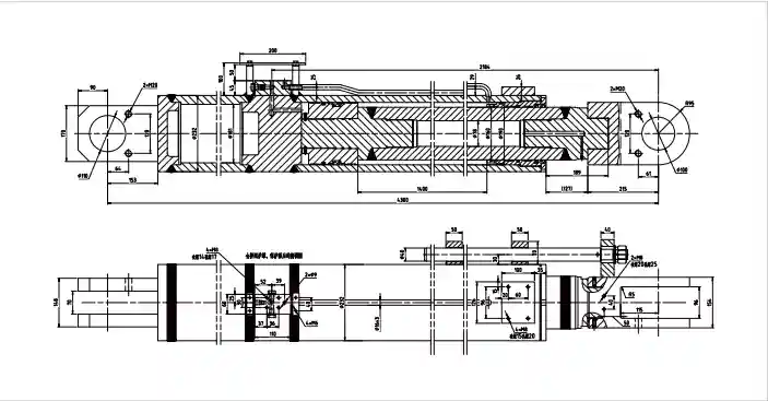
What Makes the Anti-Tip Cylinder Different From Every Other Cylinder on the Crane
Most hydraulic cylinders on a crane operate in a predictable, single-direction load cycle: extend to lift, retract to lower, hold at a fixed position. The crane boom lateral support cylinder doesn’t follow that pattern. It operates in a fundamentally different load regime — one where the primary loads are lateral rather than axial, where the cylinder may spend most of its service life locked at a fixed extension with no active cycling, and where the critical performance requirement is not force output but structural rigidity under side-load.
Notice the Φ190 bore paired with a Φ160 rod — a bore-to-rod ratio of just 1.19:1. That’s unusual. Most hydraulic cylinders use a 2:1 or larger bore-to-rod ratio to maximize push force. The near-equal dimensions on the HCYY11112019 are deliberate: when the primary threat is a side-tipping force rather than a vertical lifting load, you want maximum rod stiffness in both extension and retraction directions. The fat rod reduces the annular area differential between push and pull — giving 833 kN push and 633 kN pull — but more importantly, it raises the rod’s second moment of area, dramatically increasing resistance to lateral bending under transverse load.
The 4300 mm installation distance is the most telling specification on this cylinder. While the stroke is only 1400 mm, the cylinder spans 4300 mm across the boom’s lateral brace structure. This wide span is the geometric source of the anti-tip function: the longer the moment arm from the boom centerline to the cylinder attachment point, the smaller the force required in the cylinder to resist a given lateral tipping moment. A cylinder mounted close to the boom centerline would need to be enormously strong to do the same job — the wide-span geometry trades installation real estate for manageable cylinder loads.
The 40 MPa withstand pressure on this cylinder also needs to be understood in the context of dynamic loading. Anti-tip events — an unexpected load swing, a gust of wind, a sudden side-pull during rigging — generate impact loads rather than slow static pressure buildup. The 8.5 MPa margin above working pressure must absorb those impact spikes without triggering the relief valve, which would allow momentary lateral displacement of the boom before pressure rebuilds.
Operating Conditions Where the Boom Anti-Tip Cylinder Is Put to the Test
The HCYY11112019 is continuously loaded during every operation where lateral boom stability is at risk. That covers more scenarios than most operators think:
- Tandem and assisted lifts — where two cranes share a load and a coordination error can generate sudden lateral forces on one boom while the other takes the imbalance
- Lifts in wind-exposed environments — offshore platforms, coastal construction, and open-site infrastructure work where wind loading on a large lattice boom creates sustained lateral force at the boom tip
- Cross-slope crane travel with suspended load — where gravity acts laterally on both the load and the boom, and the anti-tip cylinder must resist the combined moment on every metre of travel
- Load swing during pick-and-carry operations — where the load pendulums laterally and the impulse load reaches the boom structure through the rigging
- Emergency stops and braking events — where inertia of the suspended load continues forward while the crane decelerates, generating transverse forces at the boom connection
Construction Details — Engineered for Lateral Rigidity, Not Just Axial Force
Cylinder Barrel
Seamless forged steel (27SiMn), precision-honed ID Ra ≤ 0.4 μm. Wall section designed for 40 MPa burst with lateral bending stress component included in FEA analysis — unlike purely axial cylinder designs.
Heavy-Section Rod
Φ160 mm 42CrMo4 rod — same diameter as the boom hoist cylinder despite a smaller bore. This is intentional: the fat rod section maximizes lateral bending stiffness (I = πd⁴/64) for anti-tip load resistance.
Gland & Bearing
Extended rod gland with bronze bearing bush, length-to-diameter ratio ≥ 1.0. The long gland bearing distributes lateral bending moments across a wider surface, preventing point loading on the rod seal under transverse forces.
Seal Package
PU/PTFE composite piston seals with anti-extrusion rings rated to 40 MPa impact pressure. Double-lip rod seal with heavy-duty scraper wiper. Rated −30 °C to +90 °C for year-round heavy construction service.
End Mounts
Heavy forged-steel clevis ends, pin bores at H7 tolerance. Spherical self-aligning bearings standard — critical for an anti-tip cylinder that experiences off-axis loading as the boom deflects under lateral force.
Load-Holding Valve
Dual pilot-operated counterbalance valves fitted on both ports — the anti-tip cylinder must hold its position under load in both extend and retract directions, since tipping threats come from either lateral side.
Crawler Crane Hydraulic Cylinder Installation Positions
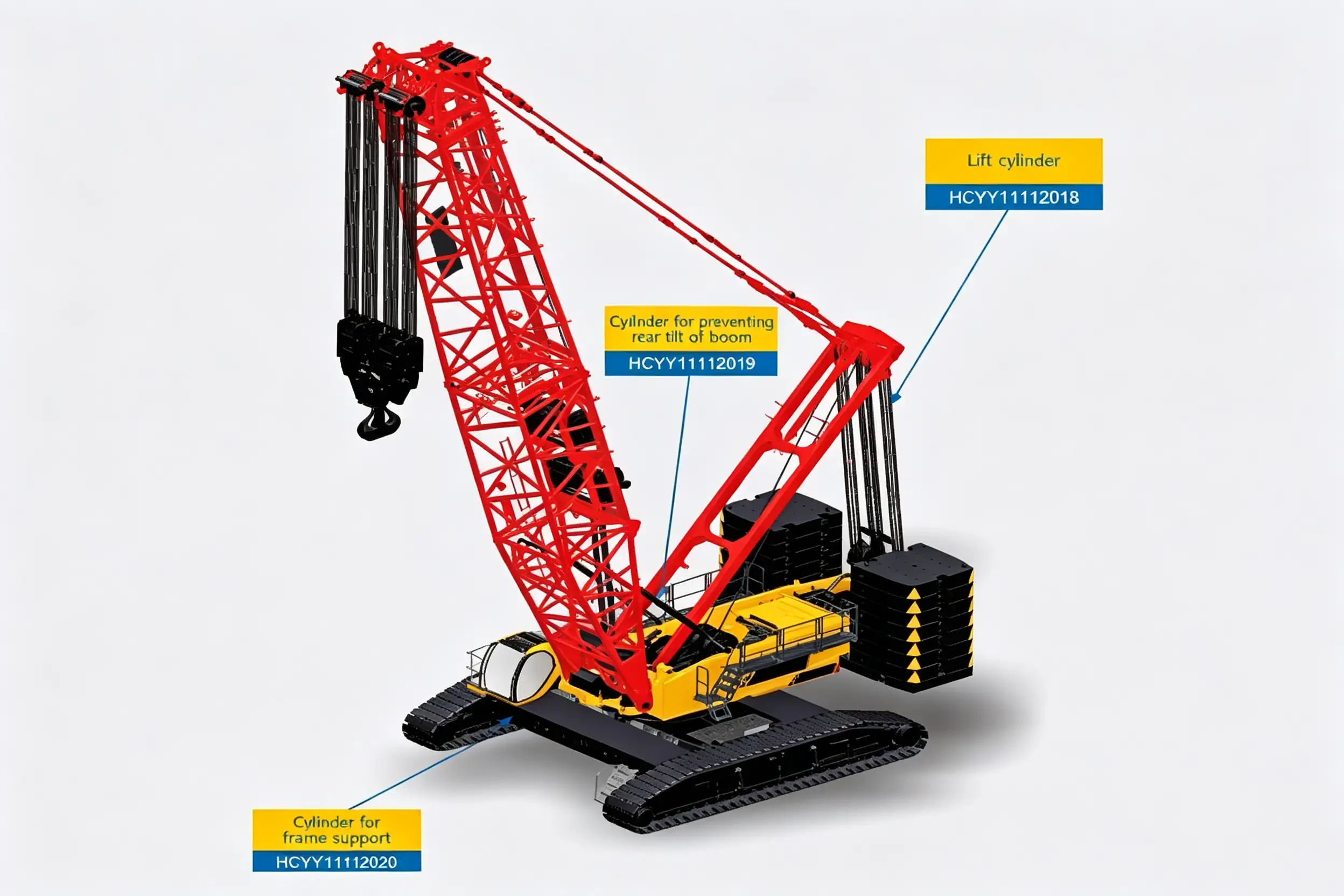
The anti-tip cylinder mounts laterally across the boom structure — its 4300 mm installation span provides the moment arm needed to resist lateral tipping forces during lifts and travel.
Installation Notes — Getting the 4300 mm Span Right
The HCYY11112019 has the largest installation distance of any cylinder in this crane system — 4300 mm pin-to-pin. That span makes alignment during installation more sensitive than on the hoist or frame cylinders:
- Measure the existing installation distance in-situ before ordering, with the boom at its normal working angle. The effective pin-to-pin dimension changes with boom angle due to geometry — confirm the measurement at the boom angle where the cylinder will most commonly operate.
- Inspect spherical bearing condition at every cylinder replacement. The self-aligning bearings in the end mounts compensate for small boom deflections — a seized bearing transmits bending moments directly into the cylinder gland and accelerates rod seal wear.
- Commission dual CBV settings independently. Both ports carry counterbalance valves; set them separately against the calculated load-induced pressure for each direction. The tipping threat is not equal from both sides in all configurations — site-specific loading conditions should inform the individual CBV settings.
- Verify cylinder alignment in the lateral plane after installation. An anti-tip cylinder that is not truly perpendicular to the boom’s tipping axis introduces a longitudinal force component that adds to — rather than resists — the hoist cylinder’s load.
- Perform a lateral load function test before returning the crane to service. Apply a controlled lateral test load to the boom and verify the cylinder holds position without drift for a minimum of 5 minutes.
Common Questions — Crawler Crane Boom Anti-Tip Cylinder
Sourcing the HCYY11112019 Anti-Tip Cylinder — or Need Urgent Supply?
We supply crawler crane boom anti-tip cylinders to crane OEMs, fleet maintenance teams, and heavy-lift contractors worldwide. Full dimensional drawings, dual-CBV configuration, hydrostatic test certificates, and individual serial-number traceability are standard. Expedited production available for confirmed urgent requirements.
Model: HCYY11112019 · Φ190×Φ160×1400 · 31.5 MPa / 40 MPa · 1400 mm stroke · 4300 mm installation distance · 820 kg