描述
Why Hooklift Trucks Need a Telescopic Cylinder — Not Just a Longer Tilt Cylinder
Here’s a question that comes up more often than you’d expect: if the tilt cylinder already has a 1925 mm stroke, why does the hooklift system need a separate telescopic hydraulic cylinder at all? The answer is geometry — specifically, the problem of getting a hook from a steeply tilted arm position to a point low enough to engage a container sitting on flat ground, without the arm itself becoming so long it becomes structurally impractical.
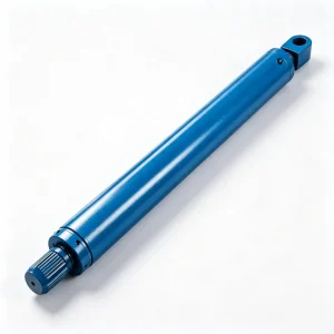
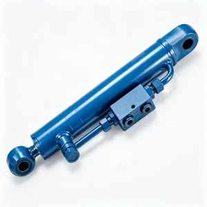
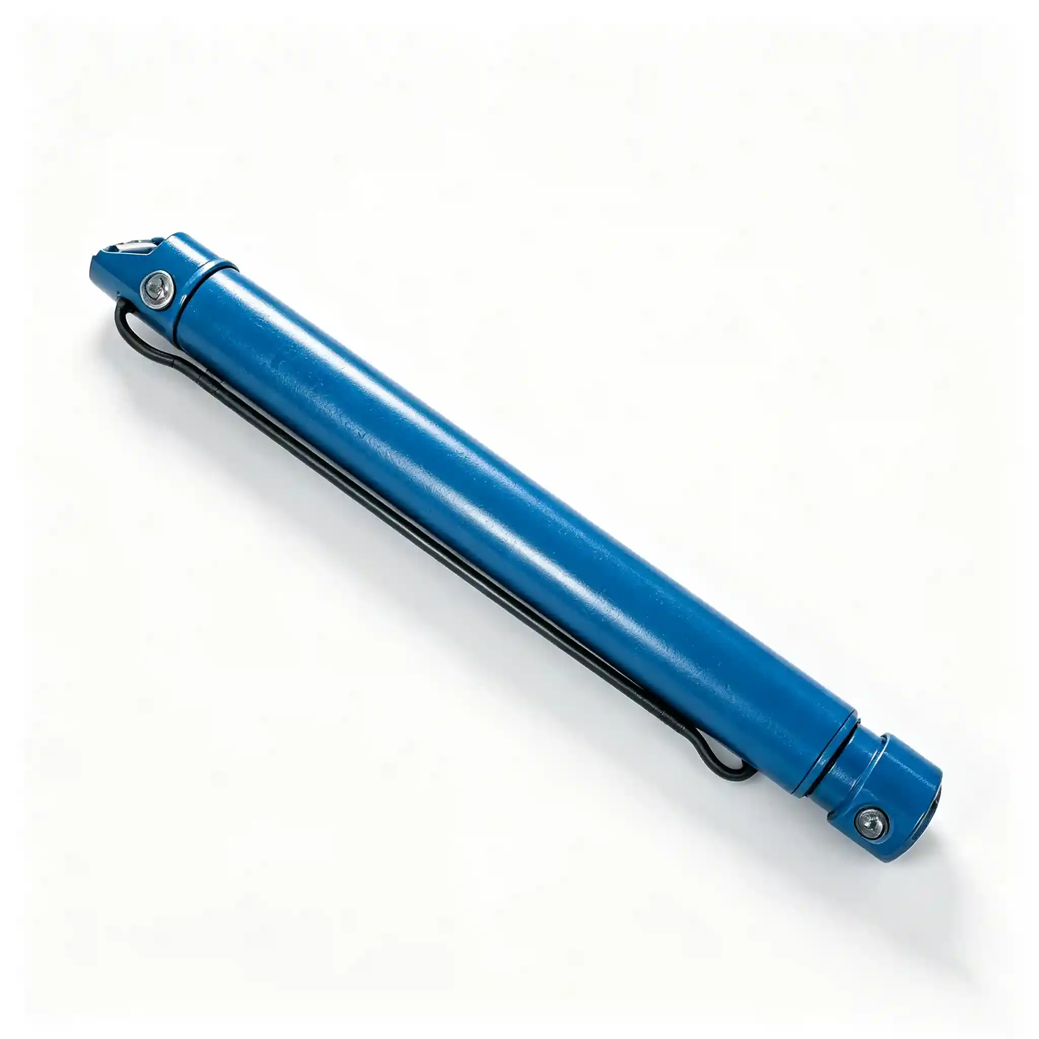
The hook lift telescopic cylinder (HCYY11112015) solves this by adding a second stage of extension that deploys independently of — or in sequence with — the tilt cylinder. With a Φ100 mm bore and a 1100 mm stroke collapsing into a 1400 mm installation distance, this cylinder extends the functional reach of the hooklift arm without adding proportional length to the subframe or the vehicle’s overall chassis overhang.
At 90 kg, the HCYY11112015 sits in the middle of the hooklift cylinder family by weight — heavier than the 4.2 kg body lock cylinder, lighter than the 290 kg tilt cylinder — which reflects its intermediate role in the load cycle. It doesn’t lift the container alone, but without it, many hooklift systems simply can’t reach far enough to engage a container that’s been set down on flat ground with any horizontal offset from the truck’s rear.
The telescoping design is also what makes the cylinder’s retracted footprint disproportionately compact: 1400 mm center-to-center when closed, yet capable of delivering 1100 mm of working stroke. That ratio — just over 1.27:1 extension factor for a single-stage telescopic — is a key packaging advantage over a conventional single-rod cylinder of equivalent stroke.
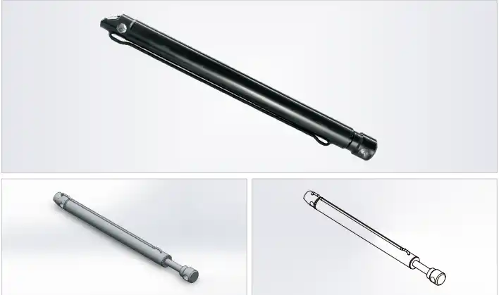
Technical Specifications — HCYY11112015 Telescoping Hydraulic Cylinder
| Parameter | Value | Engineering Context |
|---|---|---|
| Model | HCYY11112015 | Hooklift telescopic extension cylinder series |
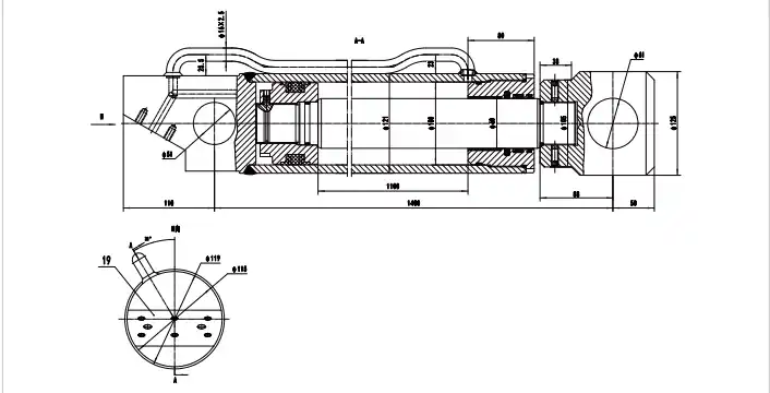
| Bore × Rod × Stroke | Φ100 × Φ60 × 1100 mm | Telescopic stage delivers 1100 mm reach from a 1400 mm closed body |
| Working Pressure | 30 MPa | Push force ≈ 236 kN at Φ100 bore / rated pressure |
| Max Withstand Pressure | 35 MPa | 17% safety margin; each stage independently tested |
| Stroke (Trip) | 1100 mm | Total extended travel across all telescopic stages |
| Installation Distance | 1400 mm | Retracted center-to-center; extension ratio ≈ 1.79× closed length |
| Weight | 90 kg | Mid-range — balanced between structural rigidity and arm inertia |
Telescopic vs. Single-Rod: The Packaging Advantage That Changes Truck Design
To understand why a telescoping hydraulic cylinder earns its place in a hooklift system, consider the alternative: a conventional single-rod cylinder with the same 1100 mm stroke would require a minimum retracted length of roughly 1600–1800 mm (depending on rod diameter and end connection design). That’s 200–400 mm more subframe length consumed by cylinder packaging alone — space that has a direct cost in vehicle chassis design, body-to-cab clearance, and legal overall vehicle length limits.
With the HCYY11112015 retracted to 1400 mm and extending to deliver 1100 mm of stroke, the extension ratio of 1.79× means the cylinder delivers nearly 80% more travel than its closed body length. This is the core value proposition of telescopic design in vehicle applications: you get the stroke you need without the chassis penalty.
The Φ100 mm outer bore and Φ60 mm inner stage are sized to maintain adequate wall thickness across both stages at 30 MPa. The 5:3 bore-to-rod ratio is a deliberate compromise between push force on the first stage (236 kN at Φ100) and pull/retraction force on the inner stage — in most hooklift systems, retraction of this cylinder is gravity-assisted by arm weight, so the pull force requirement is modest compared to the extend force needed during container engagement.
One important nuance specific to telescopic cylinders: extension sequence matters. In a two-stage telescopic, the outer (larger) stage extends first under pressure because it has the larger area and therefore lower pressure required to move. Once the outer stage reaches its end stop, pressure builds and the inner stage extends. This sequential behavior must be accounted for in the hooklift control valve timing — a poorly-tuned valve can cause the inner stage to slam its end stop, generating pressure spikes that exceed the 35 MPa withstand limit on the inner stage seals.
Where the Hooklift Telescopic Cylinder Makes the Difference
The need for a telescopic extension cylinder is most acute in hooklift configurations where the truck must engage containers in constrained or offset positions — the real-world conditions that a simple tilt-only system can’t handle:
- Urban waste collection — containers set down in tight streets or car parks where the truck can’t reverse precisely to the container centerline; the telescopic stage compensates for horizontal reach variation
- Long-container transport — 6–7 m roll-off containers where the rear-most engagement point is further from the truck than shorter skip bins; the telescopic extension closes that gap
- Multi-drop fleet operations — trucks cycling multiple containers per shift where fast, consistent arm extension reduces average loading time and operational cost
- Ground-level container pickup — flatbed-positioned containers that sit lower than standard skip feet require maximum arm extension to get the hook low enough to engage
- OEM hooklift system builders — body manufacturers designing systems for multiple chassis platforms where installation distances vary; the telescopic cylinder’s compact retracted length simplifies cross-platform fitment
Construction Details — Telescopic Stage Sealing and Surface Treatment
Outer Stage Tube
Φ100 bore, seamless cold-drawn steel (ST52/E355), precision-honed to Ra ≤ 0.4 μm. Wall thickness verified by hydrostatic test to 35 MPa before stage assembly.
Inner Stage / Rod
Φ60 mm chrome-plated inner plunger, hard chrome ≥ 20 μm on all sliding OD surfaces. Both the OD (running in the outer bore) and tip end are finished to the same tolerance class.
Stage Seal Design
Each stage carries an independent PU piston seal set plus a dedicated wiper at its gland. Inter-stage sealing is isolated so that a failure at the outer stage doesn’t immediately compromise the inner stage circuit.
End Cushioning
Hydraulic end cushions fitted at the full-extension stop of each stage, reducing end-of-stroke velocity to < 50 mm/s to prevent spike pressures and mechanical impact on the stop collar.
External Finish
Two-coat epoxy primer plus polyurethane topcoat on the outer barrel, minimum 80 μm DFT. Salt-spray rated; compatible with standard fleet wash-down procedures.
Factory Testing
Full stroke function test (3 complete cycles), hydrostatic hold at 35 MPa for 5 minutes per stage, leakage check at 30 MPa working pressure. Test certificate available on request.
Hydraulic Cylinder Mounting Position — Hooklift Truck System
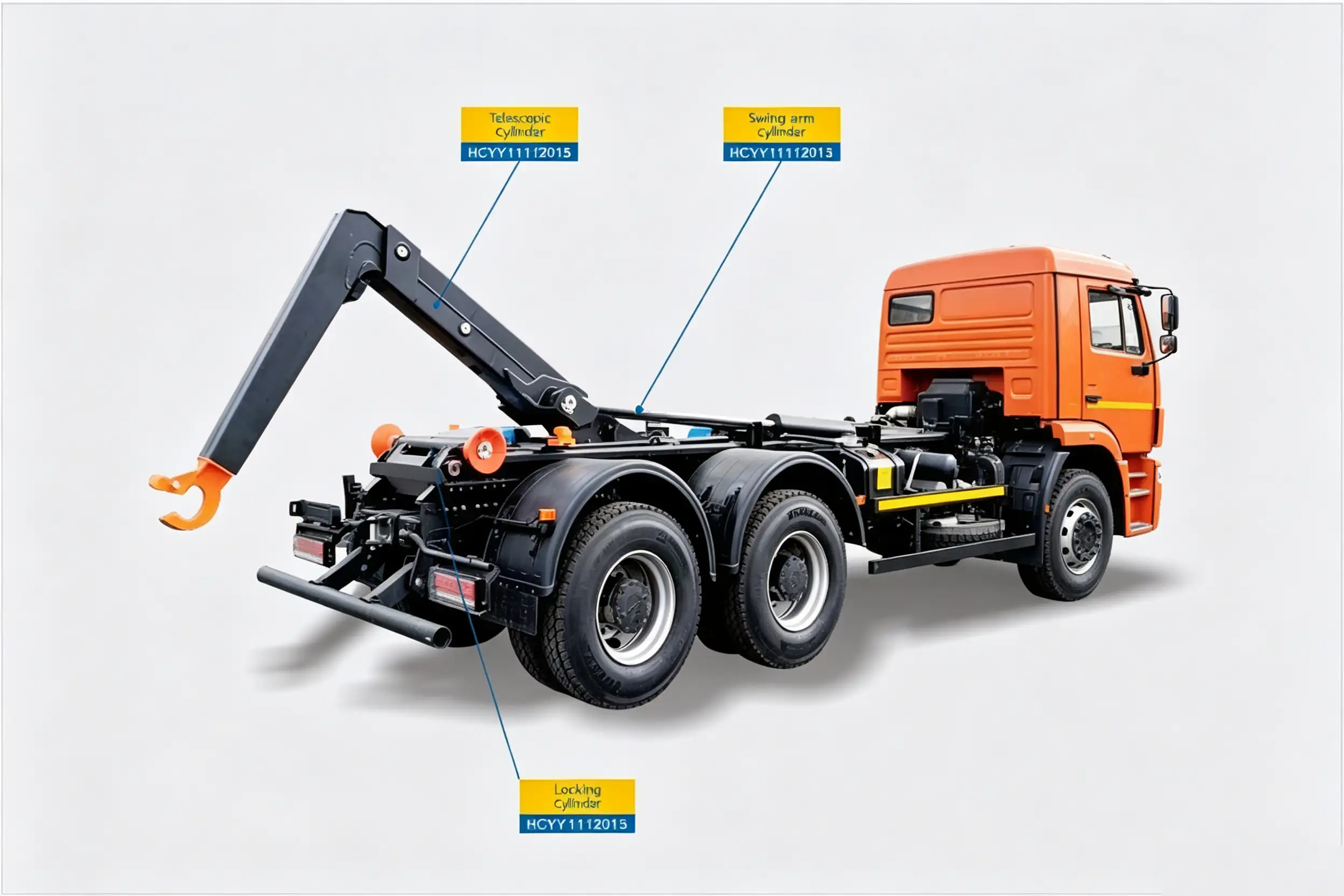
The telescopic cylinder extends the arm’s reach during container engagement, compensating for horizontal offset between the truck rear and the container pickup point.
Installation and Setup Notes for the Roll-Off Truck Telescopic Cylinder
Telescopic cylinders have a few installation considerations that don’t apply to conventional single-rod units — worth knowing before the first wrench turns:
- Port orientation is critical. Telescopic cylinders have a defined “base end” and “rod end” port arrangement that differs by design. Installing them inverted — base port up — traps air in the base chamber and causes erratic stage sequencing. Confirm port orientation against the dimensional drawing before mounting.
- Fill and bleed each stage independently. Connect only the base port line, extend the outer stage fully and hold for 30 seconds, then connect the rod-end line and retract. Repeat for the inner stage. Skipping this step leaves air in the inter-stage cavity that causes violent snap-through when the first stage reaches its stop.
- Check flow control valve settings against stage sequence. The outer stage extends first and at higher speed (larger area, same flow rate). If the flow control is set for the inner stage speed, the outer stage will be too slow; if set for the outer stage, the inner stage will over-speed into its end stop. Adjust the flow limiter with a calibrated flow meter, not by feel.
- Confirm the 1400 mm installation distance precisely. On telescopic cylinders, even a 15 mm error in installation distance shifts the arm geometry noticeably — more so than on a single-rod cylinder of the same stroke, because the compact retracted length leaves less geometric tolerance in the linkage.
- Apply load to extension, not retraction, for break-in. During the first 20 operating cycles, keep the hooklift arm unloaded during retraction strokes to allow inter-stage seals to bed in against the running surfaces without eccentric loading.
Common Questions — Hook Lift Telescopic Hydraulic Cylinder
How many stages does the HCYY11112015 have?
The HCYY11112015 is a two-stage telescopic cylinder. The outer stage (Φ100 bore) extends first, followed by the inner stage (Φ60). Total stroke across both stages is 1100 mm, achieved from a 1400 mm retracted installation length. If your application requires more than 1100 mm of total travel within a similarly compact retracted footprint, contact us — three-stage configurations are available as a custom order.
The outer stage extends but the inner stage won’t move — what’s wrong?
Four likely causes, in order of probability: (1) The outer stage isn’t fully bottomed on its end stop — residual travel prevents pressure from building high enough to move the inner stage. Confirm by watching the outer stage physically stop moving before expecting the inner stage to start. (2) The inner stage seal has failed and is bypassing — pressure won’t build across the piston regardless of what the outer stage does. (3) A flow control valve is throttling the supply line so aggressively that there isn’t enough pressure differential to sequence the inner stage. (4) Air lock in the inner stage — bleed the cylinder as described in the installation notes.
Can I replace just the inner stage, or do I need the whole cylinder?
If the damage is limited to the inner stage (bent plunger, scored chrome surface, failed piston seal), replacing only the inner stage assembly is possible and is the correct approach when the outer tube bore is still in spec. We supply inner stage replacement assemblies for the HCYY11112015 as a service part. However, if the outer tube bore shows scoring or out-of-round wear — typically caused by a bent inner stage running off-center — the whole cylinder needs replacement, since re-honing the OD bore in the field is not practical.
Does the telescopic design affect extension speed compared to a single-rod cylinder?
Yes — and this is an important tuning consideration. Because the two stages have different bore areas (Φ100 outer vs. Φ60 inner), the same pump flow rate produces different extension speeds at each stage. The outer stage moves slower (larger area, same flow = lower velocity); the inner stage moves faster (smaller area, same flow = higher velocity). This is normal and expected — but it means the arm’s movement rate is not constant through the full 1100 mm stroke. For applications where smooth, consistent arm speed is needed, a flow-divider or stage-specific flow control valve can be added to the circuit to equalize extension velocity across both stages.
What hydraulic fluid is recommended, and does it affect seal life?
The HCYY11112015 seal package is rated for mineral-base hydraulic oil meeting ISO VG 46 or VG 68 (HM or HV grade). HV grade is recommended for operations where fluid temperature varies widely — HV oil’s viscosity index additive package keeps the fluid in the correct viscosity band at both cold start (−25 °C) and high continuous-duty temperatures (up to +85 °C). Avoid fire-resistant fluids (phosphate ester or water-glycol based) unless specifically requested — the standard PU seal compound is not compatible with these fluid types and will swell and degrade within a few hundred operating hours.
Need This Telescopic Cylinder in Quantity — or a Custom Stroke?
We supply the HCYY11112015 hooklift telescopic cylinder to OEM body builders, fleet procurement teams, and hydraulic distributors across North America, Europe, and Australia. Custom stroke lengths, alternative bore configurations, and non-standard installation distances are available — contact us with your dimensional requirements and we’ll confirm feasibility and lead time.
Model: HCYY11112015 · Φ100×Φ60×1100 · 30 MPa / 35 MPa · 1100 mm stroke · 1400 mm installation distance · 90 kg