Beschrijving
Crane Outrigger Extension Hydraulic Cylinder
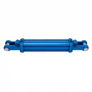
The crane outrigger extension hydraulic cylinder HCYY11112022 drives the lateral deployment of the outrigger beam — the horizontal telescoping structure that widens the crane’s effective base footprint before a lift begins. With a Φ70mm bore, a 1,237mm stroke, and a compact installation distance of just 140mm at full retraction, this cylinder is engineered for the tight packaging constraints inside folded outrigger box beams while delivering the extension force needed to slide heavy steel beams outward under loaded conditions.
Key Specifications at a Glance
- Bore × Rod × Stroke: Φ70 × Φ50 × 1237 mm
- Working Pressure: 20 MPa
- Max Withstand Pressure: 30 MPa
- Installation Distance: 140 mm
- Weight: 48 kg
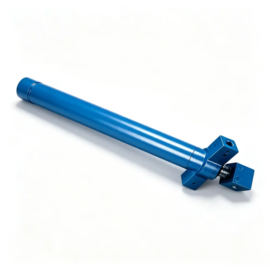
Model: HCYY11112022
How the Outrigger Beam Extension Cylinder Determines Crane Stability Before a Lift
Before any crane lift begins, the outrigger system must be fully deployed. The outrigger consists of two sequential motions: the beam extends horizontally outward to increase the support base width, and then the vertical jack cylinder drives the pad into the ground to transfer load off the wheels. The HCYY11112022 handles the first of those two motions — the lateral beam extension.
What makes this cylinder’s engineering task non-trivial is the packaging constraint. The 140mm installation distance — pin-to-pin at full retraction — means the cylinder must fit inside a folded outrigger beam structure with almost no clearance to spare. Yet once extended, it must push the outrigger beam outward 1,237mm against the combined resistance of beam weight, sliding friction in the box section, and any accumulated debris in the guide track. In wet or muddy field conditions, that friction load can be significantly higher than on a clean test rig.
At 20MPa working pressure with a Φ70mm bore, the HCYY11112022 generates approximately 77 kN of push force — sufficient to overcome beam sliding friction with an adequate force reserve for real-world contaminated conditions. The 30MPa maximum withstand pressure provides a safety margin for pressure spikes that can occur when the beam reaches end-of-travel and the operator has not yet released the control input.
At 48kg, this is a practically sized component — heavy enough to be structurally robust but light enough for a two-person replacement in the field without specialist lifting equipment.
Installation Position Diagram — HCYY11112021 / 22 / 23 on Crane
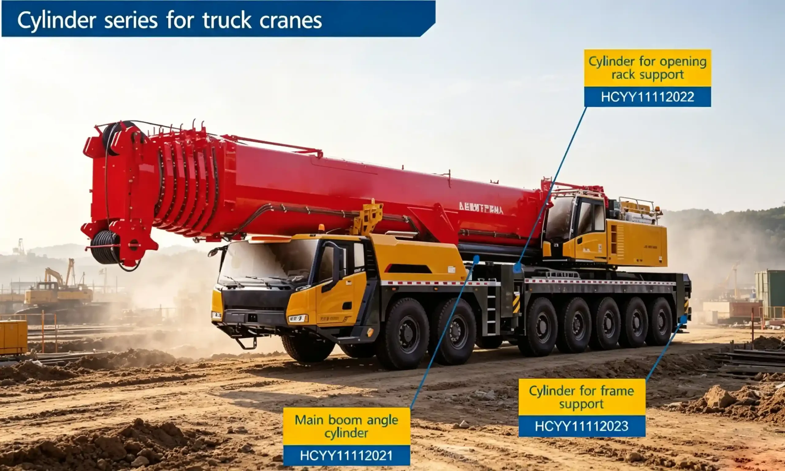
The diagram shows the mounting positions of the main boom lift cylinder (HCYY11112021), outrigger extension cylinder (HCYY11112022), and outrigger jack cylinder (HCYY11112023) within the crane chassis structure.
Full Technical Specifications for the Hydraulic Cylinder for Crane Outrigger Beam Extension
The specification values for the HCYY11112022 reflect a design optimized for longitudinal push force over a long stroke within a very compact retracted envelope. Each parameter is explained in context below.
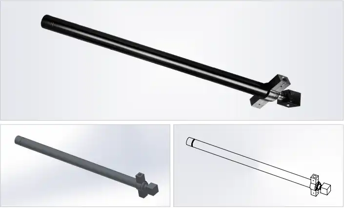
| Parameter | Value | Engineering Significance |
|---|---|---|
| Model | HCYY11112022 | Unique product identifier for procurement, spare parts ordering, and service records. |
| Specifications | Φ70 × Φ50 × 1237 mm | Bore × Rod diameter × Stroke. The Φ50mm rod is 71% of bore diameter — appropriate for a primarily push-load application where rod buckling over 1,237mm stroke must be within Euler limits. |
| Working Pressure | 20 MPa | Rated operating pressure. At Φ70mm bore (effective area ≈ 3,848 mm²), this produces approximately 77 kN of extension force — more than adequate for beam extension against field friction loads. |
| Max Withstand Pressure | 30 MPa | Proof pressure — 1.5× working pressure safety factor. This generous ratio reflects the end-of-stroke pressure spike risk when the beam contacts its travel stop. |
| Stroke | 1,237 mm | Total beam travel distance. This determines the maximum outrigger spread width achievable, which directly sets the crane’s rated lifting capacity at a given radius. |
| Installation Distance | 140 mm | Pin-to-pin dimension at full retraction. At only 140mm, this cylinder is designed to sit almost entirely within the outrigger box section when stowed — a critical packaging requirement. |
| Weight | 48 kg | Manageable by a two-person maintenance crew for field replacement. Weight is consistent with the structural requirements of a Φ70mm bore long-stroke cylinder. |
Why the 140mm Installation Distance Is the Critical Dimension for Mobile Crane Outrigger Extension Cylinder Selection
Most procurement engineers focus on bore, stroke, and pressure when selecting a replacement outrigger extension cylinder. The installation distance — specifically the retracted pin-to-pin dimension — is the parameter that most frequently causes fitment failures in the field.
At 140mm retracted installation distance, the HCYY11112022 has an unusually compact footprint relative to its 1,237mm stroke. The ratio of stroke to retracted length is approximately 8.8:1 — this is achieved through a combination of precise bore-to-wall-thickness engineering and the mounting geometry that allows the cylinder to nest inside the outrigger beam profile. If a replacement cylinder has a retracted installation distance even 20–30mm longer than the original, it may prevent the outrigger beam from fully retracting into the transport position, which creates a road width violation in jurisdictions with strict vehicle width regulations.
Conversely, a cylinder with a significantly shorter installation distance may not locate correctly in the mounting bracket geometry, creating bending moments at the pin eyes that the cylinder was not designed to sustain. Always verify the retracted installation distance — not just the stroke — when specifying an outrigger extension cylinder replacement.
How a 1,237mm Stroke Outrigger Extension Cylinder Affects Rated Crane Lift Capacity
Crane capacity charts (load charts) are based on outrigger spread width as one of the primary input variables. A wider outrigger spread increases the effective tipping fulcrum distance, which allows the crane to carry a heavier load at a given radius before the tipping moment is reached. The 1,237mm stroke of the HCYY11112022 directly determines how wide the outrigger beam can extend beyond the crane chassis.
In practice, crane operators are often required to work with partially extended outriggers when space constraints prevent full spread — in urban worksites, inside buildings, or adjacent to excavations. Each partial extension position has its own rated capacity listed in the load chart. A cylinder that cannot reach its full stroke due to seal degradation, contamination, or internal scoring effectively de-rates the crane’s capacity without any visible indication to the operator. This is why regular function testing of outrigger extension cylinders — confirming full stroke is achievable under working pressure — is a standard part of crane pre-use inspection.
Typical Applications for Crane Stabilizer Extension Cylinders in Mobile and Truck-Mounted Cranes
The HCYY11112022 is applicable across the range of mobile cranes that use H-frame or X-frame outrigger configurations. Common deployment scenarios include:
- Truck-mounted hydraulic cranes (25t–160t): The outrigger extension cylinder is one of four identical units (or two distinct pairs for front and rear outriggers) that must deploy reliably before every lift cycle. High cycle frequency makes seal durability a top priority.
- All-terrain cranes: Outrigger extension in these machines occurs on uneven terrain where the beam may be partially loaded during extension, increasing the required extension force beyond theoretical calculations.
- City cranes and compact pick-and-carry cranes: Where outrigger spread is restricted by job site geometry, full and partial extension positions must be reliably repeatable. Seal integrity and consistent stroke are critical.
- OEM crane manufacturing: For crane builders sourcing outrigger system components, consistent dimensional accuracy and batch-to-batch traceability are required for production line assembly.
- Crane fleet MRO (Maintenance, Repair & Overhaul): Replacement of cylinders with scored bores, worn rod seals, or bent rods caused by off-centre loading during beam extension in contaminated conditions.
Construction and Quality Standards for Long-Stroke Outrigger Extension Cylinders
Outrigger cylinders operate in particularly harsh conditions compared to boom lift cylinders: they are closer to the ground, exposed to road spray, mud, and debris, and typically stowed in positions where contamination can accumulate around the rod wiper seal during transit. Construction standards must address these environmental factors directly.
Rod Wiper Seal
A heavy-duty polyurethane or NBR wiper seal is fitted at the gland exit to scrape particulate contamination from the rod surface before it reaches the primary rod seal. For outrigger cylinders exposed to mud and road debris, a double-wiper configuration is preferable and available on request.
Chrome Rod Surface
The Φ50mm rod receives a hard chrome plating of 20–25μm on a polished substrate. Chrome hardness (HV 800–1000) resists the abrasive scoring that occurs when the rod is retracted with surface contamination present — the single most common cause of premature outrigger cylinder failure.
Cylinder Barrel Honing
Internal bore honed to Ra 0.2–0.4μm. At Φ70mm bore, maintaining roundness and cylindricity within 0.02mm tolerance along the 1,237mm cylinder length requires precision honing equipment — not achievable with basic boring operations.
Pin Eye Design
Clevis or spherical bearing eye ends are machined and heat-treated for wear resistance at the pivot pin interface. Spherical bearing eyes allow ±3° angular misalignment, accommodating the slight geometric variation that occurs as the outrigger beam extends and the cylinder angle shifts minutely.
External Coating
Exterior surfaces primed and topcoated with industrial epoxy. Colour can be matched to crane OEM specification. The coating system is selected for resistance to hydraulic oil, diesel, and road salt — the typical chemical exposure for vehicle-mounted crane components.
Pressure Test
Each cylinder is tested at 30MPa (max withstand pressure) with a minimum 5-minute hold at full extension and full retraction. Both positions are tested because seal loading differs between extended and retracted configurations in long-stroke cylinders.
What to Confirm When Ordering a Replacement Crane Outrigger Extension Cylinder for Your Machine
Outrigger extension cylinders are frequently ordered as replacement parts rather than OEM first-fits. To confirm the HCYY11112022 matches your application or to specify a custom variant, the following information is required:
- Retracted installation distance: Measure pin-centre to pin-centre with the cylinder fully retracted. For this model it is 140mm — confirm your chassis bracket spacing matches.
- Pin bore diameter and style: Clevis width, pin diameter, and whether spherical bearings are used at the pin eyes. Mismatched pin geometry causes fretting and accelerated wear at the mounting interface.
- Port location and thread type: On outrigger extension cylinders, port location relative to the cylinder body affects hose routing inside the beam section. Confirm port position (head end / rod end) and thread specification (SAE, BSP, metric).
- Hydraulic fluid type: Standard mineral oil seals are fitted as default. If the crane uses fire-resistant hydraulic fluid, specify fluid type for alternative seal material selection.
- Crane make, model, and outrigger position: This allows cross-reference with known dimensional data and helps avoid specification errors before manufacturing.
HCYY11112022 CAD Drawing Reference
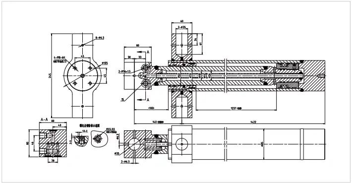
Full-dimension CAD drawing available in DXF and PDF format. Contact us with your crane model and application details to receive the drawing package for dimensional verification.
Frequently Asked Questions — HCYY11112022 Crane Outrigger Extension Hydraulic Cylinder
B2B Procurement & OEM Supply
Ready to Order or Verify Fit for the HCYY11112022?
Share your crane make and model, the retracted installation distance of your existing cylinder, and your required quantity. We will confirm dimensional compatibility, supply a CAD drawing for engineering review, and issue a formal quotation within 24–48 business hours.