
The RV Series worm gearbox — widely referenced in the global market under the NMRV designation — is the most adopted general-purpose compact worm reducer format in the world. Its defining feature is a square-block flange housing with standardised motor mounting faces on all four sides, allowing a servo, induction, or brake motor to be bolted directly onto the gearbox body without separate brackets, adapters, or base plates. The result is a compact, self-contained motor-gearbox assembly that OEM machine builders can integrate in minimal installation space and commission quickly.
This page covers the full RV Series specification: frame sizes, torque and power ratings, gear ratios, housing construction by frame size, IEC/NEMA motor interface options, output configurations, and how to read the RV model code. For a direct comparison with the WP Series cast iron gearbox, see our RV vs WP Worm Gearbox comparison guide.
RV Series and NMRV: Are They the Same Gearbox?
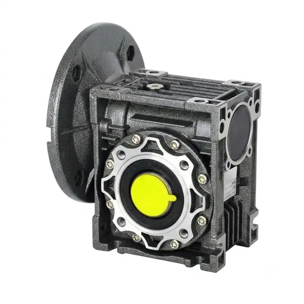
RV Series (NMRV) worm gearbox — square-block flange housing, direct IEC/NEMA motor mounting on any face
Yes — the RV Series and NMRV gearbox refer to the same product category. The difference is purely nomenclature: NMRV (Non-standard Modular Reduction Variator) is the designation that became common across Chinese and European manufacturers in the 1990s and now dominates global OEM supply chains. RV is the designation used internally by EPG Canada and a number of manufacturers to describe the same square-block, flange-housing worm gearbox format. The two are dimensionally interchangeable across the major frame sizes (025 through 150).
What distinguishes both RV and NMRV from earlier worm gearbox formats (such as the WP Series or traditional foot-mounted units) is the housing geometry: a compact cube or rectangular block with a precise IEC/NEMA motor flange machined onto one face, and optionally onto all four faces for omnidirectional motor mounting. This “motor-ready” interface eliminates the adaptor bracket and shaft coupling that traditional foot-mounted designs require.
Ordering note: When replacing an existing NMRV or NRV gearbox from any manufacturer, the EPG Canada RV Series is dimensionally compatible for the same frame size and ratio — confirm the output shaft diameter and keyway dimensions before ordering to ensure a drop-in fit.
RV Series Frame Sizes, Torque and Power Ratings
The frame size number corresponds to the worm centre distance in millimetres. Frame sizes 025 through 090 use die-cast aluminum alloy housings; from frame 110 upward, cast iron is used as the larger torques require greater wall section strength. This is the same cross-over point used across all major NMRV manufacturers.
| Frame Size | Centre Distance (mm) | Max Output Torque (Nm) | Input Power Range (kW) | Output Shaft Dia. (mm) | Housing |
|---|---|---|---|---|---|
| 025 | 25 | 4 | 0.06 – 0.09 | 11 | Aluminum |
| 030 | 30 | 8 | 0.06 – 0.12 | 14 | Aluminum |
| 040 | 40 | 25 | 0.09 – 0.37 | 18 | Aluminum |
| 050 | 50 | 50 | 0.18 – 0.75 | 25 | Aluminum |
| 063 | 63 | 100 | 0.37 – 1.5 | 28 | Aluminum |
| 075 | 75 | 200 | 0.55 – 2.2 | 35 | Aluminum |
| 090 | 90 | 350 | 0.75 – 4.0 | 40 | Aluminum |
| 110 | 110 | 600 | 1.5 – 7.5 | 50 | Cast iron |
| 130 | 130 | 980 | 2.2 – 11 | 60 | Cast iron |
| 150 | 150 | 1,760 | 4.0 – 15 | 70 | Cast iron |
* Max output torque values at lowest efficiency point. Multiply calculated application torque by your service factor before selecting frame size. Contact our team for full thermal power ratings on continuous-duty applications.
Standard Gear Ratios and Output Speed Reference
All RV Series frame sizes cover the same standard ratio range in a single stage. Dual-stage (two RV units coupled in series) extends this significantly for very low output speed requirements.
Single Stage: 5:1 to 100:1
| Ratio | Output RPM (1,450 in) | Output RPM (1,400 in) |
|---|---|---|
| 5:1 | 290 | 280 |
| 7.5:1 | 193 | 187 |
| 10:1 | 145 | 140 |
| 15:1 | 97 | 93 |
| 20:1 | 72 | 70 |
| 25:1 | 58 | 56 |
| 30:1 | 48 | 47 |
| 40:1 | 36 | 35 |
| 50:1 | 29 | 28 |
| 60:1 | 24 | 23 |
| 80:1 | 18 | 17.5 |
| 100:1 | 14.5 | 14 |
Dual Stage: Up to 3,600:1
Two RV units in series multiply ratios. Common combinations:
| Combined Ratio | Example Combination |
|---|---|
| 400:1 | 20:1 × 20:1 |
| 900:1 | 30:1 × 30:1 |
| 1,600:1 | 40:1 × 40:1 |
| 2,500:1 | 50:1 × 50:1 |
| 3,600:1 | 60:1 × 60:1 |
Note: Dual-stage efficiency is the product of both stages — verify thermal rating carefully. Provide both required ratio and duty cycle when enquiring for dual-stage units.
Housing Construction: Material, Finish, and Worm Wheel Options
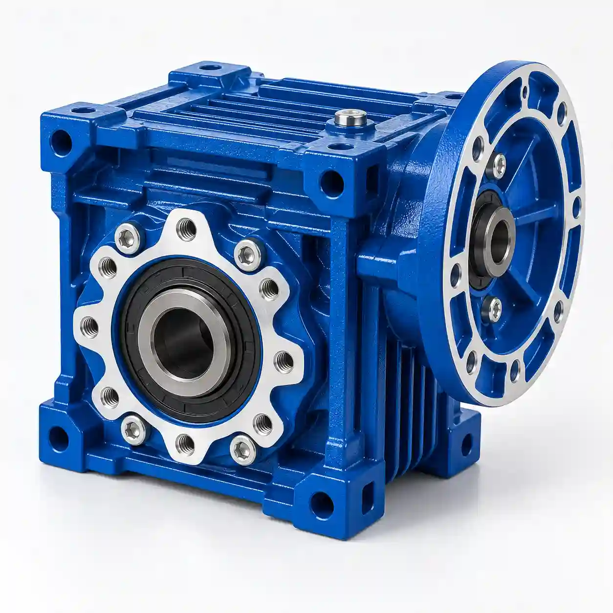
Aluminum Alloy Housing (Sizes 025–090)
- Die-cast aluminum alloy (EN-AC 46000 / ADC12 equivalent)
- Surface: shot blast, anti-corrosion treatment, phosphating
- Standard paint: RAL 5010 Gentian Blue or RAL 7035 Light Grey
- Natural corrosion resistance — no rust regardless of paint condition
- Weight: 30–40% lighter than cast iron at same frame size
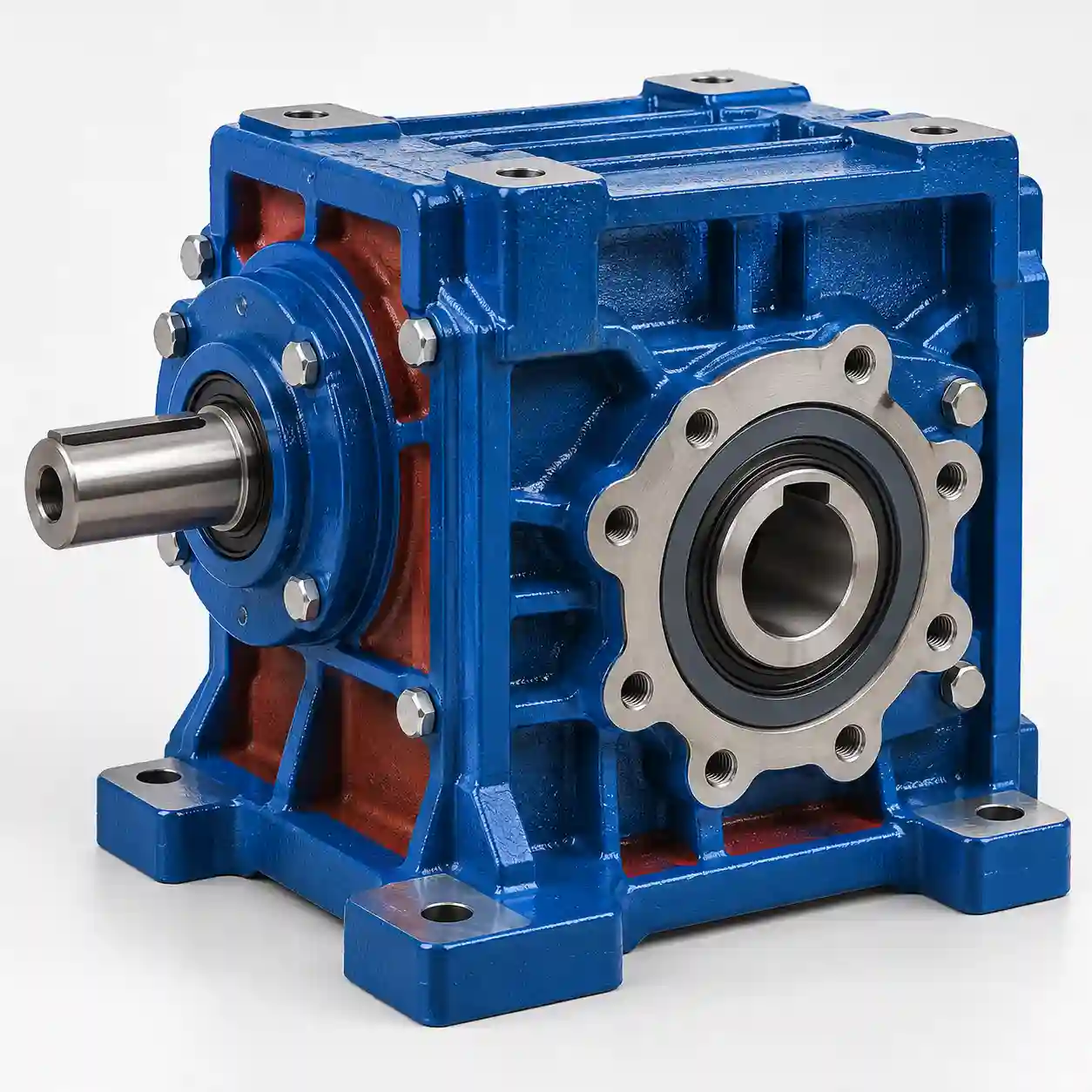
Cast Iron Housing (Sizes 110–150)
- Grey cast iron GG25 / HT250 grade
- Surface: red anti-rust primer base coat
- Standard topcoat: RAL 5010 Gentian Blue
- Higher structural rigidity for larger torque levels
- Better vibration damping for heavier duty cycles
Worm Wheel Material Options
Standard: Tin Bronze Alloy (Cu-Sn-10-3)
Centrifugally cast onto a cast iron hub. Excellent sliding-contact wear resistance with the hardened worm shaft. Standard on all frame sizes and ratios — the correct choice for general industrial service.
Option: Aluminum Bronze Alloy
Higher hardness and tensile strength than tin bronze — preferred for applications with high cycle rates, frequent reversals, or elevated ambient temperatures where wear accumulation is a concern. Specify when ordering if required.
Motor Interface: IEC and NEMA Direct Flange Mounting
The defining advantage of the RV Series housing geometry is its motor-mounting capability. The square-block housing provides four potential motor-mounting faces — in practice, one face is machined to the specified IEC or NEMA flange type, and the remaining faces are used for foot mounting or output configuration as required by the application.
The motor connects to the gearbox through a precision aluminium motor adapter (supplied with the unit), which pilots the motor shaft into a close-coupled socket on the gearbox input. A flexible spider coupling or direct quill-shaft coupling transmits torque — no alignment procedure is required beyond tightening the motor mounting bolts. This “plug-and-play” motor interface is the primary reason the RV/NMRV format became the dominant OEM worm gearbox globally.
| Motor Standard | Flange Type | Typical Motor Frame Sizes | Common Regions |
|---|---|---|---|
| IEC (International) | B14 (small flange) / B5 (large flange) | 56, 63, 71, 80, 90, 100, 112, 132 | Europe, Asia, Canada, worldwide |
| NEMA (North America) | C-face flange | 56C, 143TC, 145TC, 182TC, 184TC | USA, Canada, Mexico |
Ordering: Specify your motor standard (IEC or NEMA), motor frame size, and number of poles when ordering the RV gearbox. The correct motor adapter is then shipped with the unit. If replacing an existing NMRV gearbox, also specify the input coupling style (spider / quill-shaft) to match the existing installation.
Output Shaft Configurations
The RV Series offers five standard output configurations, covering the full range of OEM machine design requirements:
Single Solid Shaft
Standard output — one shaft extending from one side of the housing.
Double Solid Shaft
Shaft extending from both sides — for driving two loads simultaneously.
Hollow Bore Output
Gearbox slides directly over the driven shaft — saves a coupling and reduces length.
Output Flange
Bolts directly to the driven machine face — no shaft coupling required.
Torque Arm
Used with hollow bore to react housing torque — standard on shaft-mounted conveyor and indexer drives.
How to Read an RV / NMRV Gearbox Model Code
A fully specified RV gearbox model code contains five elements. Understanding each one ensures that the unit arrives ready to install without modifications:
RV 063 – 40 – B14 – 80B4
② Frame: 063
③ Ratio: 40:1
④ Flange: B14 (IEC)
⑤ Motor Frame: 80 / 4-pole
| Position | Element | What It Specifies |
|---|---|---|
| ① | RV / NMRV / NRV | Series designation — all refer to the same square-block flange format |
| ② | Frame Size (025–150) | Worm centre distance in mm — determines torque capacity and physical dimensions |
| ③ | Ratio (e.g., 40 = 40:1) | Output speed ratio — confirm against your required output RPM and motor speed |
| ④ | Motor Flange (B5 / B14 / C-face) | IEC B14 (small square flange), IEC B5 (large circular flange), or NEMA C-face — must match your motor flange type |
| ⑤ | Motor Frame (e.g., 80B4) | IEC motor frame size (80) and number of poles (B4 = 4-pole) — determines which motor adapter plate is supplied |
Request RV Series Data Sheet or Quotation
Provide your required ratio, output speed, torque, motor flange type and frame size. We will return the correct model code, dimensional drawing, motor adapter confirmation, and pricing within 24 hours.