
Every industrial worm gearbox in EPG Canada’s standard range was designed to fit the majority of applications. The majority is not all applications. When a machine’s spatial envelope won’t accept a standard center distance, when the required gear ratio falls between two catalog options, when the output shaft configuration is proprietary, or when the operating environment demands material specifications that no catalog unit carries — the non-standard worm gearbox program is the correct path forward.
This page explains when a non-standard worm gearbox is the right decision, what can be engineered to meet your requirements, the design parameters needed to generate a technical proposal, and how to structure an enquiry so EPG Canada can respond with a preliminary specification and pricing within 48 hours. For application scenarios that commonly require custom gearboxes, see our Non-Standard Worm Gearbox Applications guide.
When Should You Specify a Non-Standard Worm Gearbox?
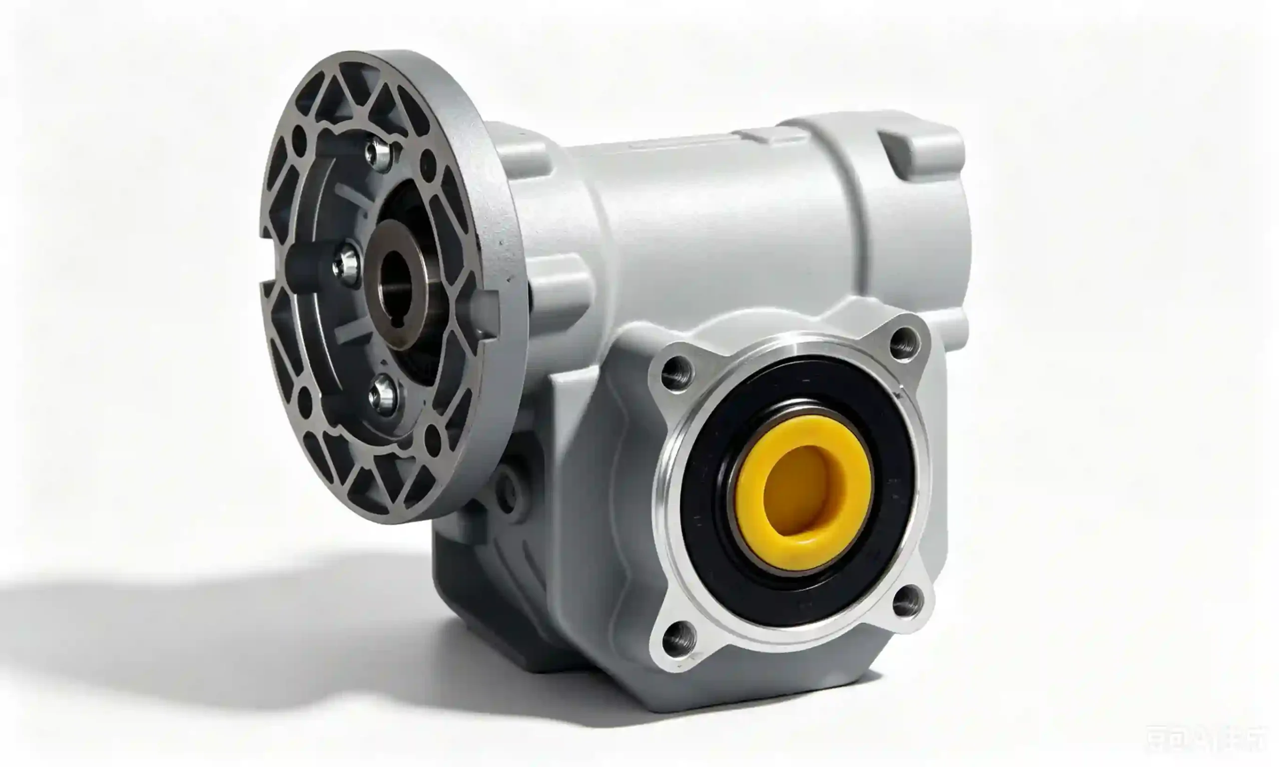
Custom worm gearboxes engineered to specific dimensional envelopes, ratios, materials, and output configurations
The decision to specify a non-standard gearbox is driven by one of five conditions — when any of these applies to your application, attempting to force-fit a catalog unit will either compromise the machine design or result in premature gearbox failure:
1. Dimensional Constraint
The machine’s spatial envelope requires a center distance, housing footprint, or shaft position that no standard unit provides. This is the most common trigger for a non-standard specification — particularly on retrofits replacing obsolete gearboxes whose dimensions were never standardised.
2. Non-Standard Ratio
The required output speed falls between catalog ratio steps — for example, a process requiring exactly 23 RPM from a 1,450 RPM motor needs a 63:1 ratio, which is not a standard catalog step. Specifying the nearest standard ratio (60:1 → 24.2 RPM, or 80:1 → 18.1 RPM) produces a process speed outside tolerance.
3. Shaft Configuration
The application needs a shaft diameter, keyway, flange bolt circle, or spline that differs from standard catalog output shafts. Common on machinery where the gearbox interfaces with a proprietary driven component — pump impellers, agitator arms, custom tooling spindles.
4. Material Requirement
The operating environment requires housing or gear material that catalog units don’t supply: stainless steel housing for salt spray or aggressive chemical exposure, food-grade certified housing material, special alloy worm shaft for high-temperature service, or upgraded sealing for submerged installation.
5. Performance Above Catalog Rating
The application’s torque, speed, or load profile exceeds what catalog units at the required ratio and frame size can deliver, and stepping up to the next frame size creates dimensional conflicts. A custom gear pair at optimised tooth geometry can increase torque capacity at the same center distance.
What Can Be Customised? Full Scope of Non-Standard Options
| Category | Standard Options | Non-Standard Options Available |
|---|---|---|
| Gear Ratio | 5, 7.5, 10, 15, 20, 25, 30, 40, 50, 60, 80, 100:1 | Any ratio from 3:1 to 120:1 in a single stage; custom multi-stage for higher ratios |
| Center Distance | 25, 30, 40, 50, 63, 75, 90, 110, 130, 150 mm (RV/Aluminum) or 40–250 mm (WP) | Any center distance within the feasible gear pair range — to match retrofit dimensional requirements |
| Output Shaft | Standard solid shaft with metric keyway; hollow bore (standard sizes) | Any diameter; inch or metric; inch keyway; spline; threaded end; custom flange; shrink disc; integrated pinion |
| Input Shaft | Hollow input for motor coupling; solid projecting shaft (WPS) | Custom input shaft for non-standard motor interface; hydraulic motor mount; PTO input; handwheel input |
| Housing Material | Aluminum alloy (small frames); cast iron (large frames) | Stainless steel 304/316; ductile iron; fabricated steel; special alloy |
| Worm Shaft Material | 45# carbon steel or 20CrMnTi alloy, carburized | Stainless steel 17-4PH; H13 tool steel for high-temperature; nitrided 42CrMo for extended wear life |
| Worm Wheel Material | Tin bronze (Cu-Sn-10-3); aluminum bronze | Phosphor bronze (higher strength); leaded bronze (improved machinability for odd pitches); engineering polymer (non-metallic, low-noise) |
| Sealing & IP Rating | IP54 standard; IP65 with Viton seals | IP67 / IP68 submersible; ATEX (explosion-proof) rated housing; H1 food-grade lubricant and seals |
| Mounting Configuration | Foot, flange, hollow bore, torque arm | Integrated base plate; custom bolt pattern; multi-axis mounting; integrated motor bracket for non-standard motor frame |
| Worm Thread Starts | Single-start (standard for high ratio) | Multi-start worm (2, 3, or 4 start) for higher efficiency at equivalent ratio; dual-lead worm for controlled backlash adjustment |
| Surface Treatment | Standard epoxy primer + PU topcoat (RAL 5010) | Hot-dip galvanizing; electroless nickel plating; anodizing (aluminum); powder coat; epoxy-phenolic for chemical resistance |
Design Parameters Required for a Technical Proposal
The completeness of the specification provided determines the accuracy and speed of the technical proposal. A complete specification generates a preliminary proposal within 48 hours; an incomplete one requires a clarification round that delays the schedule. The following parameters are required — provide as many as possible in your initial enquiry:
Multi-Start Worm: Higher Efficiency at the Same Reduction Ratio
Standard single-start worm gears achieve high reduction ratios efficiently from a packaging standpoint, but at the cost of mechanical efficiency — a 60:1 single-start worm delivers approximately 60–70% efficiency. For applications where input power is significant and running hours are high, that 30–40% friction loss represents a real operating cost.
Multi-start worm design — using 2, 3, or 4 helical thread starts on the worm shaft — raises efficiency substantially at equivalent ratios, because the worm lead angle increases with the number of starts, and efficiency rises with lead angle. A 3-start worm at 60:1 combined ratio (achieved by a 20-tooth wheel with a 3-start worm) can achieve 75–82% efficiency versus 62–68% for a single-start 60:1.
Multi-Start Worm Efficiency Reference
| Combined Ratio | Single Start (Standard) | 2-Start | 3-Start | Self-Locking? |
|---|---|---|---|---|
| 20:1 | ~74–80% | ~82–87% | ~87–92% | No |
| 40:1 | ~68–74% | ~76–82% | ~82–87% | Borderline |
| 60:1 | ~62–68% | ~72–78% | ~78–84% | Reduced |
| 100:1 | ~58–64% | ~68–74% | Not practical | Yes |
* Efficiency values approximate; actual values depend on lubricant, operating temperature, and load. Note: multi-start worms reduce or eliminate the self-locking property — confirm this is acceptable for your application before specifying.
Lead Times and Minimum Order Quantities
Non-standard gearbox lead times depend on the degree of customization required. The table below gives indicative timelines — confirm exact lead time at the quotation stage, as availability of raw material and machining capacity varies.
| Customization Level | Typical Lead Time | Min. Order Qty. | Example |
|---|---|---|---|
| Minor modification (shaft, finish) | 2–3 weeks | 1 unit | Non-standard output shaft diameter; special surface treatment; custom oil fill plug position |
| Moderate modification (ratio, material) | 4–6 weeks | 1–5 units | Non-standard ratio; stainless steel housing; upgraded sealing to IP67; special worm wheel material |
| Major modification (new housing, custom gear pair) | 6–10 weeks | Discuss with team | Non-standard center distance; multi-start worm; custom housing casting; ATEX-rated assembly |
| Full custom design from drawing | 8–14 weeks | Discuss with team | Customer-supplied 2D/3D drawing; fully engineered unit with certification requirements; OEM production quantities |
* Lead times are indicative from receipt of approved drawings and deposit payment. Prototype lead times may be longer if tooling is required for housing modifications. Rush production options are available at supplementary cost — enquire at quotation stage.
How to Submit a Non-Standard Worm Gearbox Enquiry
The fastest path from requirement to technical proposal is a structured enquiry that gives our engineering team what they need to generate an accurate specification without multiple rounds of clarification. Follow these four steps:
Compile the mandatory parameters
Input speed, output speed or ratio, output torque, duty cycle, and operating environment. Even approximate values are more useful than no values — they allow our engineers to confirm feasibility and flag any parameters that need clarification before detailed design.
Attach drawings, photos, or nameplates
A 2D sketch of the envelope, a photo of the existing gearbox nameplate, or a DXF/PDF drawing of the mounting interface cuts the proposal turnaround from 72 hours to 24 hours in most cases. If you are replacing an obsolete unit, the nameplate model number and any available dimensions are sufficient to start.
State the quantity and timing
Tell us whether you need a prototype first, the production quantity you anticipate, and any delivery deadline that drives your project. Quantity affects both pricing and whether a housing casting tool is economically justified — important to know early in the conversation.
Send by email or call to discuss
Email your specification, drawings, and quantity to [email protected] — we respond within 48 hours with a preliminary technical proposal and indicative pricing. For urgent requirements, call +1-604-719-2870 to speak with our technical team directly.
Submit Your Non-Standard Gearbox Requirements
EPG Canada responds to all custom worm gearbox enquiries within 48 hours with a preliminary technical proposal and indicative pricing.
Include: input/output speed, torque, duty cycle, dimensional constraints, and any drawings. A photo of the existing nameplate is welcome.
Frequently Asked Questions
Related Pages