
Worm gearbox failures trace back to three recurring selection errors: an under-sized frame that overheats on continuous duty, an efficiency figure that was ignored when calculating output torque, and a service factor that was set to 1.0 on an application with daily shock loading. None of these errors is difficult to avoid — they require four numbers, a straightforward calculation, and one table lookup. This guide walks through that process step by step and finishes with a complete worked example that shows the method applied from motor specification to confirmed gearbox model.
If you have already sized your application and know which product type you need, go directly to the relevant product page: Aluminum Series · WP Series · RV Series · Low Backlash Servo · Non-Standard. If you are not yet sure which type fits, see our Worm Gearbox overview.
The Four Numbers You Need Before Sizing
② Required output speed (RPM)
③ Motor power (kW or HP)
④ Application shock load level
If you have the required output torque directly (in Nm), even better — it skips the motor torque calculation. If you do not yet have the application shock classification, use the service factor table in Step 3.
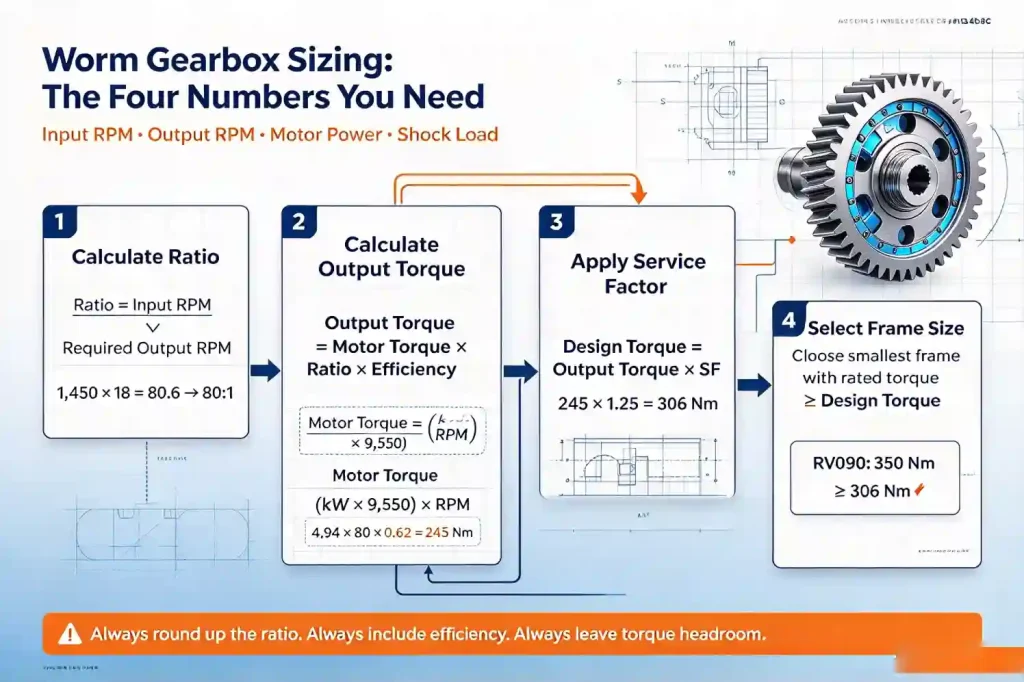
Step 1 — Calculate the Required Gear Ratio
Formula
Ratio = Input RPM ÷ Required Output RPM
Divide your motor’s rated speed by the output shaft speed your application requires. The result is the theoretical gear ratio. Round to the nearest available standard ratio step — standard single-stage worm gearboxes cover: 5, 7.5, 10, 15, 20, 25, 30, 40, 50, 60, 80, 100:1.
Rounding rule: Always round up to the next available ratio when the exact theoretical ratio falls between two standard steps — this gives a slightly lower output speed that is closer to the target than rounding down would produce. For example: 72.5:1 rounds to 80:1 (output speed 18.1 RPM), not 60:1 (output speed 24.2 RPM). If fine-tuning is needed, use a VFD to trim the motor speed to achieve the exact output RPM from a standard ratio.
Step 2 — Calculate Output Torque (Including Efficiency)
Formula
Output Torque (Nm) = Motor Torque (Nm) × Ratio × Efficiency
Motor Torque (Nm) = (Motor Power kW × 9,550) ÷ Motor Speed RPM
Critical: Do Not Omit Efficiency
Worm gearbox efficiency falls significantly with increasing ratio — from approximately 85–90% at 5:1 to 60–66% at 100:1. A simple Ratio × Motor Torque calculation overstates available output torque by 15–40%, depending on the ratio. An undersized gearbox selected on the basis of uncorrected torque will overheat, lose lubricant film strength, and fail prematurely.
Worm Gearbox Efficiency Reference by Ratio
| Ratio | Typical Efficiency (mineral oil) | Typical Efficiency (synthetic PAG) | Use This Value for Sizing |
|---|---|---|---|
| 5:1 | 85–90% | 88–93% | 0.85 |
| 10:1 | 80–85% | 84–89% | 0.80 |
| 20:1 | 74–80% | 78–84% | 0.74 |
| 30:1 | 70–76% | 74–80% | 0.70 |
| 40:1 | 68–74% | 72–78% | 0.68 |
| 50:1 | 66–72% | 70–76% | 0.66 |
| 60:1 | 64–70% | 68–74% | 0.64 |
| 80:1 | 62–68% | 66–72% | 0.62 |
| 100:1 | 60–66% | 64–70% | 0.60 |
* Use the lower-bound efficiency figure (left column) for conservative sizing on mineral oil — do not use the synthetic figure unless you have confirmed synthetic lubrication. Actual efficiency also depends on operating temperature, input speed, and load — these are representative values for initial sizing.
Step 3 — Apply the Service Factor
Formula
Design Torque = Output Torque × Service Factor (SF)
The service factor accounts for the difference between the steady-state torque calculated from motor nameplate data and the actual peak load the gearbox will experience in service — due to shock loads, start-up surges, cyclic loading, or extended continuous duty. Select the service factor from the table below based on your application’s actual operating conditions:
| Load Character | SF (up to 10 h/day) | SF (10–16 h/day) | SF (over 16 h/day) | Typical Applications |
|---|---|---|---|---|
| Smooth, uniform load | 1.00 | 1.25 | 1.50 | Fans, centrifugal pumps, light conveyors |
| Moderate shock | 1.25 | 1.50 | 1.75 | General conveyors, mixers, packaging machines, screw feeders |
| Heavy shock | 1.50 | 1.75 | 2.00 | Crushers, hammer mills, conveyor under crusher discharge, vibrating equipment |
| Extreme shock / reversing | 2.00+ | Consult | Consult | Frequent full-load reversals, impact loading, multi-start / stop cycles under full load |
Step 4 — Select Frame Size from the Torque Rating Table
Select the smallest frame size whose maximum rated output torque equals or exceeds your calculated Design Torque from Step 3. For the product type (Aluminum/RV, WP, Servo), use the corresponding specification page torque table.
Aluminum / RV Series
Frames 025–150 · Torques 4–1,760 Nm · For food, pharma, wet, OEM compact drives
WP Series
Frames 40–250 · Torques 30–4,500 Nm · For heavy-duty industrial 24/7 service
Low Backlash Servo
Sizes S1–S8 · Torques 10–1,500 Nm · For servo motors and precision positioning
Sizing tip: If your design torque is close to the maximum rating of the frame size (within 10%), step up to the next frame size. The small cost difference buys a meaningful improvement in thermal margin and service life. Never select a gearbox at exactly its rated torque for a real application — always leave headroom.
Step 5 — Verify Thermal Rating for Continuous Duty
For applications running more than 4–6 hours continuously per cycle, the thermal power rating — not the mechanical torque rating — is often the binding constraint. A gearbox has two ratings: mechanical (the maximum torque the gear pair can transmit) and thermal (the maximum continuous input power the housing can dissipate as heat without oil temperature exceeding the lubricant’s safe limit).
The thermal power rating decreases sharply with increasing ratio because higher ratios have lower efficiency and therefore generate more heat from the same input power. At 80:1 with 62% efficiency, 38% of all input power becomes heat — every kilowatt of motor input generates 380 W of heat in the gearbox oil. For continuous duty at high ratios, check the thermal rating in the product’s full specification sheet (contact our team if not shown online) and confirm that your input power does not exceed it.
Thermal Rating Checks — When Required
- Duty cycle S1 (continuous running without stops)
- Ratio 30:1 or higher with continuous duty
- Ambient temperature above 30°C
- Gearbox in an enclosed cabinet or against a wall (poor ventilation)
Remedies If Thermal Rating is Exceeded
- Step up one frame size (larger thermal mass and surface area)
- Switch from mineral to synthetic PAG oil (10–15% efficiency improvement)
- Add a cooling fan to the housing (increases thermal dissipation)
- Reduce duty cycle or add an intermittent cooling period
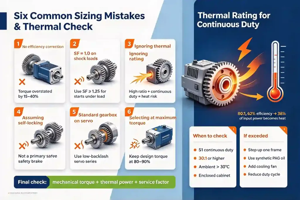
Six Common Worm Gearbox Sizing Mistakes
Calculating output torque without efficiency
Output torque = Ratio × Motor torque — without the efficiency multiplier, torque is overstated by 15–40%. This is the most common sizing error.
Service factor set to 1.0 on a shock-load application
Any application that starts under load, involves bulk material impact, or cycles frequently should use SF ≥ 1.25. SF = 1.0 is only correct for very smooth, uniform loads.
Ignoring thermal rating on continuous duty at high ratios
At 60:1 and above on continuous duty, thermal rating — not mechanical torque — is the binding constraint. Always check thermal power against your input power for continuous applications.
Assuming self-locking without verifying the ratio
Self-locking only applies at ratios of approximately 30:1 and above — and even then is not guaranteed under vibration or high temperature. Never rely on worm gear self-locking as the primary load-holding device on safety-critical vertical axes.
Using a standard worm gearbox with a servo motor
Standard worm gearboxes have 15–20 arc-minutes of backlash — invisible to the encoder but real at the output. For servo positioning applications, only the Low Backlash Servo series is appropriate.
Selecting a gearbox at its maximum rated torque
Always leave torque headroom — size the gearbox so design torque is 80–90% of rated torque at most. This headroom covers transient overloads, ageing, and the variability between nameplate and real-world motor performance.
Complete Worked Example: Food Conveyor Drive
Given Application Data
Application
Food processing belt conveyor
Motor
0.75 kW, 4-pole IEC motor, 1,450 RPM
Required output speed
18 RPM
Duty cycle
8 hours/day, moderate shock (starts under load)
Environment
Food plant — wet washdown, non-rusting required
Calculate Ratio
1,450 RPM ÷ 18 RPM = 80.6 → round up to 80:1 (standard step)
Output speed at 80:1 = 1,450 ÷ 80 = 18.1 RPM ✓
Calculate Output Torque
Motor torque = (0.75 × 9,550) ÷ 1,450 = 4.94 Nm
Output torque = 4.94 × 80 × 0.62 (efficiency at 80:1) = 245 Nm
Apply Service Factor
Moderate shock, 8 h/day → SF = 1.25
Design torque = 245 × 1.25 = 306 Nm
Select Frame Size
Design torque = 306 Nm. From the Aluminum Series torque table:
→ RV075 / Aluminum size 075: max 220 Nm ✗ Insufficient
→ RV090 / Aluminum size 090: max 350 Nm ✓ Selected
Design torque (306 Nm) = 87% of rated (350 Nm) — within headroom guideline ✓
Final Selection + Product Type Confirmation
Gearbox: RV090 (or Aluminum Series size 090), ratio 80:1, IEC B14 motor adapter for 71B4 frame
Product type: Aluminum/RV Series — food plant environment (wet, non-rusting) ✓
Duty check: 8 h/day intermittent — thermal rating verification recommended at 80:1 (contact our team)
Lubricant: NSF H1 food-grade synthetic PAG (food plant, risk of incidental contact)
Need Help with Your Sizing Calculation?
Send us your motor data, required output speed, torque, and application description. Our engineers will confirm the correct frame size, type, and lubricant specification within 24 hours — no charge for the recommendation.
Frequently Asked Questions
Select Your Worm Gearbox